background image

8

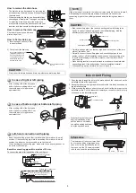
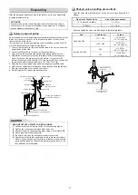
How to remove the drain cap

Clip the drain cap by needle-nose 
pliers and pull out.

How to remove the drain hose

•  The drain hose can be removed by removing the 

screw securing the drain hose and then pulling out 
the drain hose.

•  When removing the drain hose, be careful of any 

sharp edges of steel plate. The edges can injuries.

•  To install the drain hose, insert the drain hose 

fi

 rmly until the connection part contacts with heat 

insulator, and then secure it with original screw.

How to 

fi

 x the drain cap

1)  Insert hexagon wrench (4 mm) 
  in a center head.

2)  Firmly insert the drain cap.

Firmly insert the drain hose and drain cap; otherwise, water may leak.

CAUTION

Drain hose

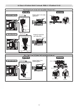
Left-hand connection with piping

•  Bend the connecting pipe so that it is laid within 43 mm above the wall 

surface. If the connecting pipe is laid exceeding 43 mm above the wall 
surface, the indoor unit may unstably be set on the wall.

  When bending the connecting pipe, make sure to use a spring bender so 

as not to crush the pipe.

Bend the connecting pipe within a radius of 30 mm.

To connect the pipe after installation of the unit (

fi

 gure)

80


520 mm

420 mm

43 mm

Liquid side

Gas side

(To the forefront of 

fl

 are)

Outward form of indoor unit

R 30 mm (Use polisin (polyethylene)

core or the like for bending pipe.)

Use the handle of screwdriver, etc.


NOTE

If the pipe is bent incorrectly, the indoor unit may unstably be set on the wall.
After passing the connecting pipe through the pipe hole, connect the 
connecting pipes to the auxiliary pipes and wrap the facing tape around 
them.

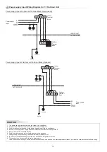
In case of right or left piping

•  After scribing slits of the front panel 

with a knife or a making-off pin, cut 
them with a pair of nippers or an 
equivalent tool. 

In case of bottom right or bottom left piping

•  After scribing slits of the front panel 

with a knife or a making-off pin, cut 
them with a pair of nippers or an 
equivalent tool. 

Slit

Slit

CAUTION

•  Bind the auxiliary pipes (two) and connecting cable with facing tape 

tightly. In case of leftward piping and rear-leftward piping, bind the 
auxiliary pipes (two) only with facing tape.

Indoor unit

Connecting cable

Auxiliary pipes

Installation plate


•  Carefully arrange pipes so that any pipe does not stick out of the rear 

plate of the indoor unit.

•  Carefully connect the auxiliary pipes and connecting pipes to one 

another and cut off the insulating tape wound on the connecting pipe 
to avoid double-taping at the joint; moreover, seal the joint with the 
vinyl tape, etc.

•  Since dewing results in a machine trouble, make sure to insulate both 

connecting pipes. (Use polyethylene foam as insulating material.)

•  When bending a pipe, carefully do it, not to crush it. 

1

2

1

Hook here.

Installation plate

Hook

Press

(unhook)

Push

Push

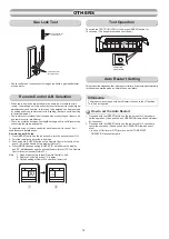
Indoor Unit Fixing

•  For detaching the indoor unit 

from the installation plate, 
pull the indoor unit toward 
you while pushing its bottom 
up at the speci

fi

 ed parts.

1.  Pass the pipe through the hole in the wall and hook the indoor unit on the 

installation plate at the upper hook.

2.  Swing the indoor unit to right and left to con

fi

 rm that it is 

fi

 rmly hooked up on 

the installation plate.

3.  While pressing the indoor unit onto the wall, hook it at the lower part on the 

installation plate. Pull the indoor unit toward you to con

fi

 rm that it is 

fi

 rmly 

hooked up on the installation plate.

The lower part of indoor unit may 

fl

 oat, 

due to the condition of piping and you 
cannot 

fi

 x it to the installation plate. In 

that case, use the 

!

 screws provided 

to 

fi

 x the unit and the installation plate. 

Information

!


Screw

!


Screw

Do not apply lubricating oil
(refrigerant machine oil) 
when inserting the drain 
cap. Application causes 
deterioration and drain
leakage of the plug.

Insert a hexagon wrench 
(4 mm).

No gap

Summary of Contents for RAS-18J2AVRG-E

Page 1: ...AIR CONDITIONER SPLIT TYPE INSTALLATION MANUAL Indoor unit RAS 18J2KVRG E RAS B22J2KVRG E RAS B24J2KVRG E Outdoor unit RAS 18J2AVRG E RAS 22J2AVRG E RAS 24J2AVRG E R32 or R410A 1120650169 ...

Page 2: ...e 9 OUTDOOR UNIT 9 Installation Place 9 Precautions about Installation in Regions with Snowfall and Cold Temperatures 9 Draining the Water 10 Refrigerant Piping Connection 10 Evacuating 11 ELECTRICAL WORKS 12 Wiring Connection 12 In Case of Indoor Unit Connect With 1 1 Outdoor Unit 13 In Case of Indoor Unit Connect With Inverter Multi System IMS 15 OTHERS 16 Gas Leak Test 16 Remote Control A B Sel...

Page 3: ...s not require admission or repeated hospital treatment 2 Property damage means greater damage which affects assets or resources For general public use Power supply cord and connecting cable of appliance use shall be at least polychloroprene sheathed flexible cord design H07RN F or cord designation 60245 IEC66 Shall be installed in accordance with national wiring regulations This appliance must be ...

Page 4: ...Y ELECTRIC PARTS MAY BE DAMAGED CHECK THE EARTH WIRE THAT IT IS NOT BROKEN OR DISCONNECTED BEFORE INSTALLATION DO NOT INSTALL NEAR CONCENTRATIONS OF COMBUSTIBLE GAS OR GAS VAPORS FAILURE TO FOLLOW THIS INSTRUCTION CAN RESULT IN FIRE OR EXPLOSION TO PREVENT OVERHEATING THE INDOOR UNIT AND CAUSING A FIRE HAZARD PLACE THE UNIT WELL AWAY MORE THAN 2 M FROM HEAT SOURCES SUCH AS RADIATORS HEATERS FURNAC...

Page 5: ...erants may not contain an odour Do not pierce or burn as the appliance is pressurized Do not expose the appliance to heat flame sparks or other sources or ignition Else it may explode and cause injury or death A special tool for the R32 or R410A refrigerant is required for installation Thickness of copper pipes used R32 must be more than 0 8 mm Never use copper pipes thinner than 0 8 mm After comp...

Page 6: ...ter or other moisture before installation could result in electric shock Do not store it in a wet basement or expose to rain or water After unpacking the unit examine it carefully for possible damage Do not install the unit at place where leakage of flammable gas may occur In case gas leaks and accumulates at surrounding of the unit it may cause of fire Do not install in a place that can increase ...

Page 7: ...s the filter 1 Recommend to use vacuum to clean by sucking the dusts which stick or dip inside the filter or use the blower to blow the dust go out through the filter 2 If necessary to use water to clean simply use the plain water to wash the filter dry with the sunlight for 3 4 hours or until it completely dry Nevertheless use hair drier to dry it However washing with water it may reduce the perf...

Page 8: ...parately with insulation not together 8 mm thick heat resisting polyethylene foam 1 Batteries 7 Flat head wood screw 4 Remote control holder Vinyl tape Apply after carrying out a drainage test Wireless remote control Saddle Extension drain hose Not available provided by installer Shield pipe Attach to the front panel Air filter Hook Installation plate Hook 50 mm or more 300 mm or more 170 mm or mo...

Page 9: ...no obstacles near the air inlet and outlet A place which allows easy installation of the piping to the outdoor unit A place which allows the front panel to be opened The indoor unit shall be installed at least 2 5 m height Also it must be avoided to put anything on the top of the indoor unit CAUTION 5 4 45 5 7 Side view Top view Indoor unit R e c e p t i o n r a n g e Remote control Remote control...

Page 10: ...fter scribing slits of the front panel with a knife or a making off pin cut them with a pair of nippers or an equivalent tool Slit Slit CAUTION Bind the auxiliary pipes two and connecting cable with facing tape tightly In case of leftward piping and rear leftward piping bind the auxiliary pipes two only with facing tape Indoor unit Connecting cable Auxiliary pipes Installation plate Carefully arra...

Page 11: ...ll the unit such as to avoid admission of wind 4 Installation in the following places may result in trouble Do not install the unit in such places A place full of machine oil A saline place such as the coast A place full of sulfide gas A place where high frequency waves are likely to be generated as from audio equipment welders and medical equipment Strong wind Do not use the supplied drain nipple...

Page 12: ...nserted properly if their outer circumferences lift up or the caps catch on or wedge against something Water proof rubber caps supplied with the outdoor unit Base plate Drain nipple 2 Install the drain nipple and a commercially available drain hose with 16 mm inside diameter and drain off the water For the position where the drain nipple is installed refer to the installation diagram of the indoor...

Page 13: ...2 kgf m H17 14 18 N m 1 4 to 1 8 kgf m A H Hexagon wrench is required Service Port Cap Valve Rod Cap Evacuating After the piping has been connected to the indoor unit you can perform the air purge together at once AIR PURGE Evacuate the air in the connecting pipes and in the indoor unit using a vacuum pump Do not use the refrigerant in the outdoor unit For details see the manual of the vacuum pump...

Page 14: ...er rear plate bushing and air inlet grille on the indoor unit Cord clamp Terminal cover Screw Screws Air inlet grille Front panel 1 Remove the valve cover the electric parts cover and the cord clamp from the outdoor unit 2 Connect the connecting cable to the terminal as identified by the matching numbers on the terminal block of indoor and outdoor unit 3 Insert the power cord and the connecting ca...

Page 15: ...al block 3 50 mm 10 mm 70 mm 10 mm Connecting cable Connecting cable connect to 1 2 3 Terminal block L N 1 2 3 Earth line Power supply cable Connecting cable Earth line Earth line Stripping length of the connecting cable Power Supply Input at Outdoor Unit Terminal Block Optional Indoor Unit Outdoor Unit Connecting cable connect to L 2 3 Terminal block L N 1 2 3 Earth line Connecting cable Connecti...

Page 16: ...ncorrect or incomplete wiring is carried out it will cause an ignition or smoke 9 This product can be connected to main power supply Connection to fixed wiring A switch which disconnects all poles and has a contact separation at least 3 mm must be incorporated in the fixed wiring Power supply input Wiring Diagram for 1 1 Outdoor Unit Indoor Terminal Block Indoor Terminal Block Power supply input P...

Page 17: ...connected to main power supply Connection to fixed wiring A switch which disconnects all poles and has a contact separation at least 3 mm must be incorporated in the fixed wiring Power supply input Wiring Diagram for Inverter Multi System IMS Indoor Terminal Block Power input Outdoor Terminal Block Chassis Chassis Power input at Outdoor Terminal Block In Case of Indoor Unit Connect With Inverter M...

Page 18: ...he remote control signal simultaneously and operate In this case the operation can be preserved by setting either one remote control to B setting Both are set to A setting in factory shipment The remote control signal is not received when the settings of indoor unit and remote control are different There is no relation between A setting B setting and A room B room when connecting the piping and ca...

Page 19: ...e quantity of residue shiny metal dust or other wear residue or mixture of foreign matter is observed trouble will occur 8 When temporary installation and removal of the air conditioner are repeated such as when leased etc 9 If the type of refrigerator oil of the existing air conditioner is other than the following oil Mineral oil Suniso Freol S MS Synthetic oil alkyl benzene HAB Barrel freeze est...

Page 20: ...1120650169 ...

Reviews: