High Wall, Heat Pump Type
Service Manual
104
Toshiba
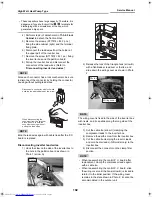
CN300: Outdoor fan motor (3P: white)
CN704: 4-way valve coil (2P: white)
CN600: TE sensor (2P: white)
CN700: Pulse motor valve coil (6P: white)
CN603: TS sensor (3P: white)
CN602: TO sensor (2P: white)
CN601: TD sensor (3P: white)
CN703: Heater for antifreeze (2P: red)
(-ND only)
CN705: (1-2 cylinder switching valve)(2P: red)
REQUIREMENT
Connect wires to the correct connectors. Failure to do
so may result in a malfunction.
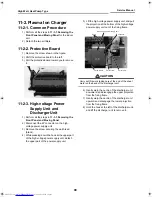
2) Remove the control board assembly from the
control P.C. board base with the heat sink
assembled with the control board assembly
with screws.
NOTE
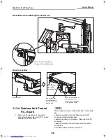
Release the four claws on the control P.C. board
base, hold the heat sink, and then remove the
assembly upward
.
3) Remove the five screws securing the heat sink
and the control board assembly.
4) Attach a new control board assembly.
NOTE
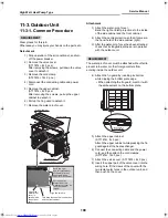
• When attaching the new control board assembly,
insert the board properly into the board holder
groove
.
• After the board is replaced and accommodated in
the inverter box,
securely clamp the portions that
were clamped before replacement with cable
ties
to prevent wires from touching hot areas or
metal edges.
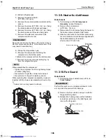
11-3-5. Side Cabinet
Side cabinet (right)
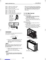
1) Perform the step of detachment in
11-3-2.
Front Cabinet
and all the steps in
11-3-3.
Control Board Assembly
.
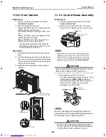
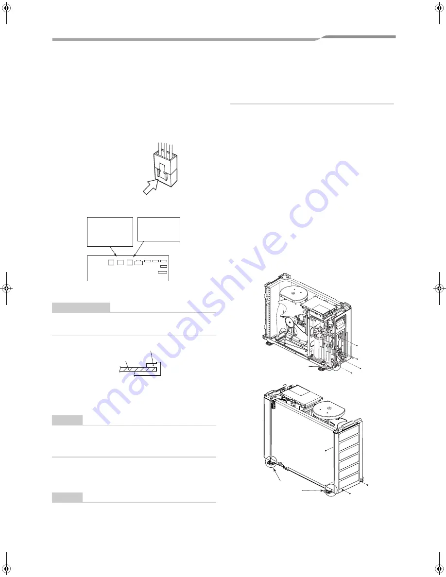
2) Remove the screws (ST1TØ4 × 8L 5 pcs.)
fixing the bottom plate and the packed valve
fixing plate.
Side cabinet (left)
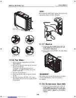
1) Perform the step of detachment in
11-3-2.
Front Cabinet
.
2) Remove the screw (ST1TØ4 × 8L) fixing the
side cabinet (left) and the heat exchanger.
3) Remove the screws (ST1TØ4 × 8L) fixing the
side cabinet (left) and the bottom plate.
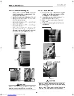
CN300, CN700,
CN704, CN600,
CN601, CN602,
CN603, CN703
and CN705
are connectors with
a lock mechanism.
Disconnect them
while pressing the
portion indicated
by the arrow.
(Solder side)
CN704
4-way valve coil
Connector color
:
White
CN705
1-2 cylinder
switch-over valve
Connector color
:
Red
CN703 CN705 CN704 CN300 CN603 CN601 CN600
CN602
CN700
Control P.C. board
Control P.C. board base
Hook the claw
to the bottom plate.
A
Hook the claw
to the bottom plate.
B
C
(07, 10)
+00A08-010_01EN_SVM_HighWallHeatPump.book Page 104 Wednesday, March 4, 2009 11:22 AM

