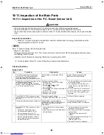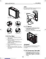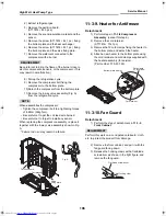
High Wall, Heat Pump Type
Service Manual
91
Toshiba
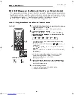
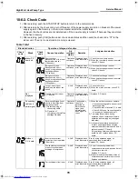
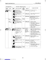
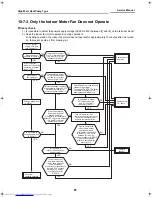
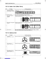
10-11-2.Indoor Unit (Other Parts)
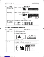
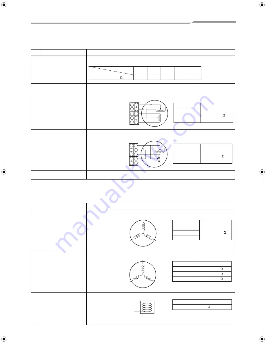
10-11-3.Outdoor Unit
No.
Part name
Checking procedure
1
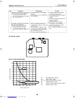
Room temp. (TA) sensor
Heat exchanger (TC) sensor
Heat exchanger (TCj) sensor
Disconnect the connector and measure the resistance value with tester.
(Normal temp.)
2
Remote controller
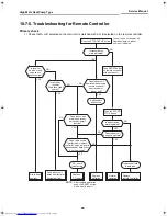
Refer to
10-7-5.Troubleshooting for Remote Controller
3
Louver motor (right, left,
Horizontal)
MP24Z3N
Measure the resistance value of each winding coil by using the tester.
(Under normal temperature 25°C)
4
Louver motor (Moving panel)
MP24Z4N
Measure the resistance value of each winding coil by using the tester.
(Under normal temp. 25°C)
5
Indoor fan motor
Refer to
10-7-3.Only the Indoor Motor Fan Does not Operate
and
10-7-4.Indoor Fan Motor
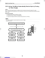
Automatically Starts to Spin by Turning on Power Supply
in
10-7.
No.
Part name
Checking procedure
1
Compressor
(Model : DA111A1FD-21F)
Measure the resistance value of each winding by using the tester.
2
Outdoor fan motor
(Model : ICF-140-43-4R)
Measure the resistance value of winding by using the tester.
3
4-way valve coil (Cooling/
heating switching)
(Model : VHV-01AZ535A1)
Measure the resistance value of winding by using the tester.
Temperature
Sensor
TA, TC, TCj (k )
10°C
20°C
25°C
30°C
40°C
20.7
12.6
10.0
7.9
4.5
5
4
3
2
1
White
Yellow
Yellow
Yellow
Yellow
5
4
3
2
1
Position
1 to 2
1 to 3
1 to 4
1 to 5
Resistance value
250 ± 20
5
4
3
2
1
White
Yellow
Yellow
Yellow
Yellow
5
4
3
2
1
Position
1 to 2
1 to 3
1 to 4
1 to 5
Resistance value
200 ± 20
Red
White
Black
Position
Red - White
White - Black
Black - Red
Resistance value
1.24 to 1.38
Under 20°C
Red
White
Black
Position
Red - White
White - Black
Black- Red
Resistance value
20 to 22
20 to 22
20 to 22
Under 20°C
Resistance value
7.2 ± 0.36
Under 20°C
Connector : White
+00A08-010_01EN_SVM_HighWallHeatPump.book Page 91 Wednesday, March 4, 2009 11:22 AM

