background image

– 44 –

FILE NO. SVM-02009

8-6. How to Set Remote Control Selector

Switch

When two indoor units ae installed in seperated rooms,
there is no need to change the selector switch.

<Remote control selector switch>

When two indoor units are installed in the same
room or the adjacent two rooms, they may be
controlled simultaneously with a single remote
control. To prevent this, set either unit and its remote
control to B setting. (Both units are set to A setting
before shipment.)

The remote control signal is not recived when the
indoor unit setting is different from the remote
control one.

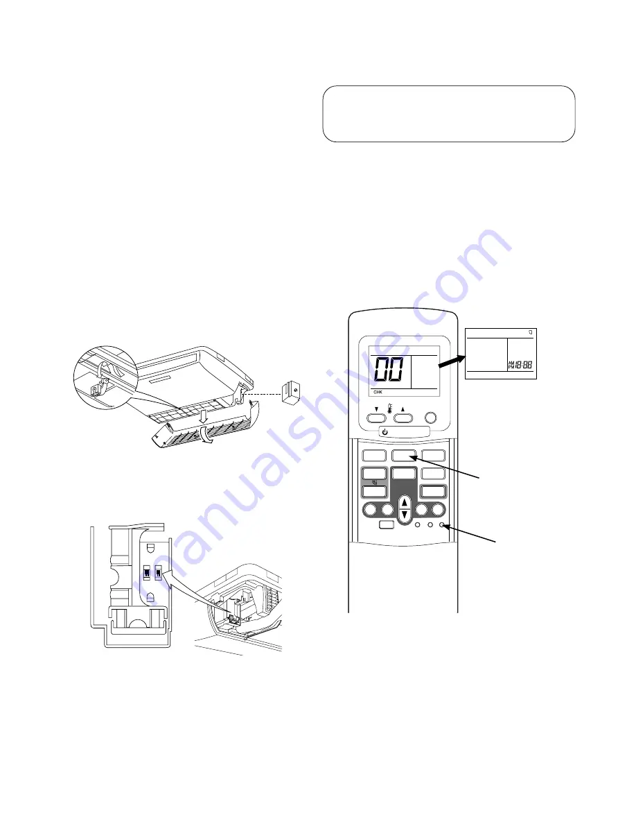
1. Set the remote control selector switch with the

indoor unit.

1) Turn the circuit breaker of the main power switch off

before setting the selector switch.

2) Remove the Air inlet grille. (Refer to page 35, 8-4-2)

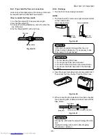
Fig. 8-6-1

3) Select the terminal of selector switch from [A

position] to [B position].

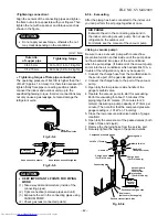
Fig. 8-6-2

REMOCON

INST

ALL

A

C

B

F

2. Set the remote control selector switch with the

remote control

[B] is indicated on the liquid crystal display when
setting remote control selector switch to B. [A] is not
indicated on the display even if the selector switch
is set to A.

1) Load the remote control with the batteries.

2) Press the [CHECK] button using something with

sharp point. (The preset temperature on the remote
control changes to [00].)

3) Press the [MODE] button while pressing the

[CHECK] button, [B] is indicted at the right of the
present temperature display.

To reset the switch to the [A] setting, press the
[MODE] button again while pressing the [CHECK]
button.

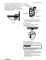
Fig. 8-6-3

3. Confirm that the indoor unit can operate with the

new setting.

PRESET

FAN

MODE

Hi-POWER

ON

OFF

SET

CLR

ECO

AUTO

TIMER

CLOCK CHECK

RESET

FILTER

FIX

SWING

MEMO

START/STOP

A

B

A

B

[MODE] button

[CHECK] button

Summary of Contents for RAS-18UA-ES

Page 1: ...RVICE MANUAL AIR CONDITIONER UNDER CEILING CONSOLE TYPE RAS 18UFHP ES RAS 18UAH ES RAS 18UFP ES RAS 18UA ES RAS 24UFHP ES RAS 24UAH ES RAS 24UFP ES RAS 24UA ES FILE NO SVM 02009 24 Class Apr 2002 18 Class ...

Page 2: ...1 RAS 18UFHP ES RAS 18UAH ES 5 2 RAS 18UFP ES RAS 18UA ES 5 3 RAS 24UFHP ES RAS 24UAH ES 5 4 RAS 24UFP ES RAS 24UA ES 6 CONTROL BLOCK DIAGRAM 6 1 RAS 18UFHP ES RAS 24UFHP ES 6 2 RAS 18UFP ES RAS 24UFP ES 7 OPERATION DESCRIPTION 7 1 Outline of Air Conditioner Control 7 2 Description of Operation Circuit 7 3 Hi POWER Mode 7 4 High Temperature Limit Control 7 5 Low Temperature Limit Control 7 6 Defro...

Page 3: ...C Board 9 9 Troubleshooting for Remote Control 10 PARTS REPLACEMENT 10 1 Indoor Unit 10 2 Outdoor Unit RAS 18UAH ES RAS 18UA ES 10 3 Outdoor Unit RAS 24UAH ES RAS 24UA ES 11 EXPLODED VIEWS AND PARTS LIST 11 1 Indoor Unit E Parts Assy 11 2 Indoor Unit 11 3 Outdoor Unit RAS 18UAH ES 11 4 Outdoor Unit RAS 18UA ES 11 5 Outdoor Unit RAS 24UAH ES 11 6 Outdoor Unit RAS 24UA ES This air conditioner is cha...

Page 4: ...connection Liquid side size mm 6 35 Interconnection Connection type Flare connection pipe Maximum length m 15 1 One way 20 2 25 2 Maximum height m 8 10 difference INDOOR UNIT RAS 18UFHP ES RAS 18UFP ES RAS 24UFHP ES RAS 24UFP ES Width mm 1093 Dimensions Height mm 633 Depth mm 208 Net weight kg 23 Evaporator type Finned tube Indoor fan type Multi blade fan High fan m3 h 800 830 800 900 930 900 Air ...

Page 5: ...AS 24UFHP ES RAS 24UAH ES RAS 18UFP ES RAS 18UA ES RAS 24UFP ES RAS 24UA ES 1 No need to charge 15m or less 15m or less refrigerant 2 Need to charge Over 15m up to 20m 20g m Over 15m up to 25m 20g m refrigerant Temperature Condition JIS C9612 1994 Cooling Heating Indoor unit inlet air temperature DB 27 C 20 C WB 19 C 12 C Outdoor unit inlet air temperature DB 35 C 7 C WB 24 C 6 C ...

Page 6: ...t system For stud bolt 8 10 For stud bolt 6 Grille air inlet Back Body Installation plate Mount plate M10 Suspention bolt Wireless remote control Knock out system 200 Min 1093 1015 742 450 20 20 330 165 7 4 70 Min 633 460 57 18 160 633 208 1093 UNDER CEILING CONSOLE INSTALLATION ...

Page 7: ...or fixing outdoor unit 6 11x14 holes For 8 10 anchor bolt 25 Drain oulet Fan guard Handle 538 300 90 600 830 160 91 54 90 50 Installation dimension 100 or more 600 or more 600 or more 100 or more 325 Air inlet Air inlet 4x 11x14 for 8 10 anchor bolt Service Port Electric Parts cover Liquid side Flare 6 35 Gas side Flare 12 70 344 420 ...

Page 8: ...ch 12 12 364 A Detail Drawing 25 Drain outlet 12x18 hole 52 68 4 12x18 holes for 8 10 anchor bolt Handle Handle Mounting dimension of anchor bolt 600 100 or more 600 or more 600 or more 100 or more Air outlet 4 12x18 for 8 10 anchor bolt Service Port Electric Parts cover Liquid side Flare 6 35 Gas side Flare 12 70 A 600 ...

Page 9: ...7 8 9 10 10 5 3 5 3 1 1 1 1 1 1 2 2 CN100 WHI GRY GRY CN101 1 1 2 2 3 3 1 2 3 3 3 6 6 3 3 2 2 1 1 1 1 2 3 3 1 2 3 L N 1 2 3 BLK BLK CN01 HEAT EXCHANGER SENSOR TC 1 1 2 2 TRANSFORMER DISCHARGE PIPE SENSOR TD HEAT EXCHANGER SENSOR TE MAIN P C BOARD MCC 1275 COMPRESSOR FAN MOTOR INDOOR TERMINAL BLOCK INDOOR UNIT OUTDOOR TERMINAL BLOCK OUTDOOR UNIT POWER TERMINAL BLOCK POWER SUPPLY 220 240V 50 Hz CN06...

Page 10: ...CEIVE AND INDICATION PARTS 1 2 3 1 2 3 4 5 6 4 5 6 7 8 9 7 8 9 10 10 5 3 5 3 1 1 1 1 1 1 2 2 CN100 WHI GRY GRY CN101 1 1 2 2 3 3 1 2 3 3 3 6 6 3 3 2 2 1 1 BLK BLK CN01 HEAT EXCHANGER SENSOR TC 1 1 2 2 COLOR IDENTIFICATION BRW BROWN RED RED WHI WHITE YEL YELLOW BLU BLUE BLK BLACK GRY GRAY PNK PINK ORN ORANGE GRN YEL GREEN YELLOW GRN GREEN PUR PURPLE J401 ORN RED PNK YEL BRW BLU BLU BLU BLU BLU BLU ...

Page 11: ...5 3 5 3 1 1 1 1 1 1 2 2 CN100 WHI GRY GRY CN101 1 1 2 2 3 3 1 2 3 3 3 6 6 3 3 2 2 1 1 1 1 2 3 3 1 2 3 L N 1 2 3 BLK BLK CN01 HEAT EXCHANGER SENSOR TC 1 1 2 2 TRANSFORMER DISCHARGE PIPE SENSOR TD HEAT EXCHANGER SENSOR TE MAIN P C BOARD MCC 1275 COMPRESSOR FAN MOTOR INDOOR TERMINAL BLOCK INDOOR UNIT OUTDOOR TERMINAL BLOCK OUTDOOR UNIT POWER TERMINAL BLOCK POWER SUPPLY 220 240V 50 Hz CN06 CN08 CN07 C...

Page 12: ...5 6 4 5 6 7 8 9 7 8 9 10 10 5 3 5 3 1 1 1 1 1 1 2 2 CN100 WHI GRY GRY CN101 1 1 2 2 3 3 1 2 3 3 3 6 6 3 3 2 2 1 1 BLK BLK CN01 HEAT EXCHANGER SENSOR TC 1 1 2 2 CAPACITOR CAPACITOR 3 1 2 3 1 2 L N POWER SUPPLY 220 240V 50Hz 220V 50Hz For RAS 18UAX T2 RAS 24UAX T SPARK KILLER MAGNETIC RELAY FAN MOTOR INDOOR UNIT POWER TERMINAL BLOCK OUTDOOR UNIT BLK BLK BLK BLK BLK RED RED CHASSIS GRN YEL GRN YEL FE...

Page 13: ...ver motor MP35EA12 Output Rated 2W 10poles 1phase DC 12V 4 2 Outdoor Unit RAS 18UAH ES No Parts name Type Specifications Output Rated 1500W 2poles 1phase 220 240V 50Hz 1 Compressor PA225X3F 4L Winding resistance Ω Red Black White Black at 20 C 1 35 2 68 Output Rated 65W 6poles 1phase 220 240V 50Hz 2 Fan motor for outdoor HF 240 42A1 Winding resistance Ω Red Black White Black at 20 C 176 2 290 5 3 ...

Page 14: ... 4 Outdoor Unit RAS 24UAH ES No Parts name Type Specifications Output Rated 2200W 2poles 1 phase 220 240V 50Hz 1 Compressor PA290X3F 4MS Winding resistance Ω Red Black White Black at 20 C 1 07 2 20 Output Rated 51W 6poles 1phase 220 240V 50Hz 2 Fan motor for outdoor KPG6 71SB5P T1 Winding resistance Ω Red Black White Black at 20 C 64 4 127 4 3 Running capacitor SK45FMP3 5U2 AC 450V 3 5µF for fan m...

Page 15: ...ite Black at 20 C 1 07 2 20 Output Rated 51W 6poles 1phase 220 240V 50Hz 2 Fan motor for outdoor KPG6 71SB5P T1 Winding resistance Ω Red Black White Black at 20 C 64 4 127 4 3 Running capacitor SK45FMP3 5U2 AC 450V 3 5µF for fan motor 4 Running capacitor SK42CMP45U1 AC 420V 45µF for compressor 5 Magnetic relay CLK 35J 220 240V 50Hz 4 5 Outdoor Unit RAS 24UA ES ...

Page 16: ...h temperature limit control operation is included 50Hz Standard pressure P MPaG Surface temp of heat exchanger interchanging pipe T C Fan speed indoor Ambient temp conditions DB WB C Indoor Outdoor Evaporator Indoor unit Multi blade fan Cooling Heating Muffler 4 way valve Heating Cooling Compressor Condenser Propeller fan Outdoor unit Capillary tube 1 0x1500S Capillary tube 1 7x700S PA225X3F 4L Ac...

Page 17: ... Ambient temp conditions DB WB C Indoor Outdoor Standard pressure P MPaG Surface temp of heat exchanger interchanging pipe T C Indoor unit Multi blade fan Compressor Accumulator Condenser Propeller fan Outdoor unit PA225X3F 4L O D 6 35 mm Packed valve 12 70 Packed valve T P Refrigerant R 410A 1 20 Kg Evaporator 0 49m Connecting pipe 6 35 mm Mark means check points of Gas Leak O D 12 70 mm 0 39m Co...

Page 18: ...h temperature limit control operation is included 50Hz Standard pressure P MPaG Surface temp of heat exchanger interchanging pipe T C Fan speed indoor Ambient temp conditions DB WB C Indoor Outdoor Evaporator Indoor unit Multi blade fan Cooling Heating Muffler 4 way valve Heating Cooling Compressor Condenser Propeller fan Outdoor unit Capillary tube 2 0x700S PA290X3F 4MS Cooling Heating Mark means...

Page 19: ...Ambient temp conditions DB WB C Indoor Outdoor Standard pressure P MPaG Surface temp of heat exchanger interchanging pipe T C Evaporator Indoor unit Multi blade fan Compressor Condenser Tank Propeller fan Outdoor unit Capillary tube 2 0x600S PA290X3F 4MS Cooling O D 6 35 mm Packed valve 12 70 Packed valve 6 35 0 49m Connecting pipe 6 35 mm T P Refrigerant R 410A 1 60 Kg Mark means check points of ...

Page 20: ...itiallizing Circuit Clock Frequence Oscillator Circuit Power Supply Circuit Noise Filter Relay RY401 Louver ON OFF Signal Serial Signal Communication Hi POWER Display FILTER Sign Display PRE DEF Sign Display TIMER Display Louver Driver Functions Louver Control 3 minute Delay at Restart for Compressor Motor Revolution Control Processing Temperature Processing Timer Drain Pump ON OFF Serial Signal C...

Page 21: ...ver Initiallizing Circuit Clock Frequency Oscillator Circuit From Outdoor Unit Relay RY401 Relay RY04 Louver ON OFF Signal Compressor Hi POWER Display FILTER Sign Display FAN ONLY Sign Display TIMER Display Louver Driver Functions Louver Control 3 minute Delay at Restart for Compressor Motor Revolution Control Processing Temperature Processing Timer Drain Pump ON OFF Compressor ON OFF Remote Contr...

Page 22: ...to the outdoor unit controller The outdoor unit controller receives operation commands from the indoor unit and operates the outdoor fan motor and the compressor 1 Role of indoor unit controller The indoor unit controller receives the operation commands from the remote control and executes them Temperature measurement at air inlet of the indoor unit by the indoor temperature sensor Temperature set...

Page 23: ...OTE 1 The values marked with 1 are calculated and controlled by the difference in motor speed between M and L Fig 7 2 1 Setting of air flow FAN AUTO 2 ECO and Hi Power operation cannot be set 7 2 2 Cooling operation MODE button on the remote control is set to the cooling operation 1 The compressor 4 way valve outdoor fan and operation display on the remote control are controlled as shown in Fig 7 ...

Page 24: ...rolled as shown in Fig 7 2 4 Fig 7 2 4 2 The microcontroller turns the compressor on and off at the regular intervals 4 to 6 minutes While the compressor is turning off the indoor fan motor operates in the SUPER LOW position The pattern of operation depending on the relation between room temperature and preset temperatures is shown in Fig 7 2 5 Fig 7 2 5 3 FAN button on the remote control is set t...

Page 25: ...perature reaches a level at which another mode is selected 2 Temporary Auto When the TEMPORARY button on the indoor unit is pushed the preset temperature is fixed at 24 C and the indoor unit is controlled as shown in Fig 7 2 9 Fig 7 2 9 4 0 1 Room temp Preset temp C Cooling operation The louver moves to the position same as Hi POWER operation Cooling operation Fan only operation Heating operation ...

Page 26: ...ing mode except the preset temperature is higher 2 C 4 The Hi POWER mode can not be set in Dry or Fan only operation 7 4 High Temperature Limit Control The microcontroller detects the indoor heat exchanger temperature to prevent pressure of a refrigerating cycle from increasing excessively The compressor and outdoor fan motor are controlled as shown in Fig 7 4 1 Fig 7 4 1 7 5 Low Temperature Limit...

Page 27: ... not set if the power is off Push the TEMPORARY button located in the center of the front panel continuously for three seconds The unit receives the signal and beeps three times The unit then restarts operating automatically in the event of power supply being accidentally shut down When the unit is on standby Not operating When the unit is in operation Operation Motions Push TEMPORARY button for m...

Page 28: ...ton on the indoor unit Note If TEMPORARY button is pushed while the filter check lamp is not indicating the indoor unit will start the Automatic Operation When the unit is on standby Not operating Operation Motions Push TEMPORARY button for more The unit is on standby than three seconds The unit starts to operate The orange lamp is on After approx three seconds The unit beeps three times The lamp ...

Page 29: ... are also required Accordingly special tools are required for the new refrigerant R 410A as shown below For connecting pipes use new and clean piping materials with high pressure withstand capabilities designed for R 410A only and ensure that water or dust does not enter Moreover do not use any existing piping as its pressure withstand may be insufficient and may contain impurities New Refrigerant...

Page 30: ...properly earthed Appliance shall be installed in accordance with national wiring regulations If you detect any damage do not install the unit Contact your TOSHIBA dealer immediately CAUTION Exposure of unit to water or other moisture before installation could result in electric shock Do not store it in a wet basement or expose to rain or water After unpacking the unit examine it carefully for poss...

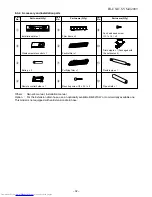
Page 31: ... 6 Zeolite filter 7 Purifying filter Air filter 5 Filter frame 2 Wireless remote control 4 Remote control holder 9 Pan head wood screw Electric parts cover Extension drain hose 100 mm or more 600 mm or more 100 mm or more 600 mm or more 600 mm or more 24 Class Loop the connective cable about 100 mm in diameter and 300 350 mm long Vinyl tape Apply after carrying out a drainage test 600 mm or more 6...

Page 32: ...ith fixing bolts and nuts if the unit is likely to be exposed to a strong wind Use 8 mm or 10 mm anchor bolts and nuts If it is necessary to drain the defrost water attach Drain nipple to the bottom plate of the outdoor unit before installing it 600 mm 325 mm 52 mm 120 mm 600 mm 340 mm 64 mm 120 mm Part Code A B C Q ty One each 1 One each Parts name Refrigerant piping Liquid side 6 35 mm Gas side ...

Page 33: ...e filter x 1 Purifying filter x 1 Mounting screw 4 x 25 s x 8 Part No 5 6 7 8 Part name Q ty Pan head wood screw 3 1 x 16 s x 2 Drain nipple x 1 Packaged with the outdoor unit Flexible pipe x 1 Pipe shield x 1 Part No 9 Others Owner s manual Installation manual Option For the Extension drain hose use an optionally available RB 821SW or commercially available one This model is not equipped with an ...

Page 34: ...gerant from being charged each port diameter has been changed Charge hose In order to increase pressure withstand strength hose materials and port size have been changed to 1 2 UNF 20 threads per inch When purchasing a charge hose be sure to confirm the port size Electronic balance As pressure is high and gasification speed is fast for refrigerant charging it is difficult to read the indicated val...

Page 35: ...ch as a curtain that may block the signal from the indoor unit Do not install the remote control in a place exposed to direct sunlight or close to a heating source such as a stove Keep the remote control at least 1 m apart from the nearest TV set or stereo equipment This is necessary to prevent image disturbances or noise interference The location of the remote control should be determined as show...

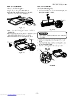
Page 36: ...ove the Panel arms from the Front panel Fig 8 4 4 1 1 2 2 5 3 3 8 4 3 After installation Install the Air inlet grille 1 Insert the three Panel arms on the Air inlet grille and fix each securely by screws Fig 8 4 5 CAUTION The screws that fixed with Panel arms must not be loose 2 Set the Air inlet grille arm to the axis of the Front panel 3 Insert the Grille stopper to the correct position and fix ...

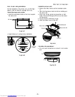
Page 37: ...sion bolts into the metal fittings of the indoor unit 3 Set to nuts spring washers and washers on both sides of the metal fittings and then move the indoor unit backward 4 Secure it with the M10 Nuts 4pcs 5 Attach the Side covers to the unit Fig 8 4 9 Condition for installation The unit must not decline more than 15 mm in either axis Fig 8 4 10 240 mm or more 235 mm or more 15 mm 15 mm 140 330 101...

Page 38: ...hose installation The piping direction can be 4 ways as illustrated The Drain hose is only one way Fig 8 4 11 How to install the Drain hose 1 Remove the two screws and the Drain band 2 Cut a slit for the drain hose hole Fig 8 4 12 3 Place the Drain hose on the U shape space and secure it with the Drain band and two screws Fig 8 4 13 Rear piping hole 80 Ceiling Wall Ceiling 175 mm or more 140 mm Sl...

Page 39: ...l Insert clip anchors for appropriate Mounting screws 8 NOTE Secure four corners and lower parts of the Installation plate 1 with 6 to 8 mounting screws to install it 390 mm or more 375 mm or more Rear piping hole 80 Floor REMOCON INSTALL A C B F 140 633 320 160 742 1093 60 Projection 15 mm or less 8 8 8 8 8 Mounting screw 4 x 25 s s s s s Clip anchor local parts 5 mm dia hole Anchor bolt Install ...

Page 40: ...5 1 Remove the Terminal cover and the Cord clamp 2 Insert the connecting cable into the pipe hole on the wall 3 Insert the connecting cable fully into the Terminal block and secure it tightly with the screw Tightening torque 1 2 N m 0 12kgf m 4 Fix the connecting cable by the Cord clamp with two screws 5 Fix the Terminal cover Stripping length of the connecting cable Fig 8 4 26 NOTE Use strand wir...

Page 41: ...0 3 When connecting the Extension drain hose insulate the connecting part of Extension drain hose with the Pipe shield Fig 8 4 31 CAUTION Arrange the drain pipe for proper drainage from the unit Improper drainage can result in dew dropping Provided by customer Extension drain hose Inside the room Drain hose Pipe Shield 8 4 7 Pipe shield for flare nut connection Joints in liquid and gas pipes of th...

Page 42: ...ION 1 Install the outdoor unit without anything blocking the air discharging 2 When the outdoor unit is installed in a place always exposed to strong wind like a coast or on a high storey of a building secure the normal fan operation using a duct or a wind shield 3 Especially in windy area install the unit to prevent the admission of wind 4 Installation in the following places may result in troubl...

Page 43: ...curely tighten the caps on the packed valves Fig 8 5 6 Tightening connection Align the centers of the connecting pipes and tighten the flare nut as far as possible with your fingers Then tighten the nut with a spanner and torque wrench as shown in the figure CAUTION Do not apply excess torque otherwise the nut may crack depending on the conditions Tightening torque of flare pipe connections The op...

Page 44: ...Service port 4 mm Same as Gas side Pipe side A Tightening torque 50 to 62 N m 5 0 to 6 2 kgf m 16 to 18 N m 1 6 to 1 8 kgf m 9 to 10 N m 0 9 to 1 0 kgf m No need to charge refrigerant Need to charge refrigerant 15 m or less Over 15 m up to 20 m 20g m 15 m or less Over 15 m up to 25 m 20g m A Hexagonal wrench is required Stripping length of connecting cable Fig 8 5 8 Fig 8 5 9 CAUTION Wrong wiring ...

Page 45: ...efer to page 35 8 4 2 Fig 8 6 1 3 Select the terminal of selector switch from A position to B position Fig 8 6 2 REMOCON INSTALL A C B F 2 Set the remote control selector switch with the remote control B is indicated on the liquid crystal display when setting remote control selector switch to B A is not indicated on the display even if the selector switch is set to A 1 Load the remote control with...

Page 46: ...ll make a short beep Fig 8 8 2 8 8 3 Auto restart setting This product is designed so that after a power failure it can restart automatically in the same operating mode as before the power failure Information The product was shipped with Auto Restart function in the off position Turn it on as required How to set the auto restart Press and hold the TEMPORARY button for about 3 seconds After 3 secon...

Page 47: ...ation starts 6 The outdoor fan motor stops in the Heating operation 7 The compressor is not turned on even though the room temperature is in the range that the compressor is turned on 8 The operation mode changes in the Auto matic operation 9 The Fan only operation continues in the Automatic operation 10 The Hi POWER operation does not work No Operation of Air Conditioner Descriptions The OPERATIO...

Page 48: ...mpressor is defective Symptom Check Primary judgement 9 3 Primary Judgement 9 3 1 Role of indoor unit controller The indoor unit controller receives the operation commands from the remote control and executes them Temperature measurement at the air outlet of the indoor heat exchanger by the indoor temperature sensor Temperature setting of the indoor heat exchanger by the heat exchanger sensor Louv...

Page 49: ...ec Alphanumeric characters are used for the check code is 5 is 6 is A is B is C is D 2 Press TIMER 8 button If there is no fault with a code the indoor unit will beep once Pi and the display of the remote control will change as follows 00 01 02 1d 1E 22 Check the unit with all 35 check codes 00 to 22 as shown in Table 9 4 1 Press TIMER 9 button to change the check code backwards If there is a faul...

Page 50: ...p on the indoor unit blinks when error is defected The lamp on the indoor unit blinks when error is defected The lamp on the indoor unit blinks when error is defected And it returns to the normal condition when recovering from errors The lamp on the indoor unit blinks when error is defected The lamp on the indoor unit blinks when error is detected 1 Check the indoor thermo sensor TA 2 Check the in...

Page 51: ...ES NO YES NO YES NO Does four way valve operate properly Is TC sensor resistance value 10kΩ at 25 C normal Does coil terminal have 220 240 V in heating operation Are circuit wires normal Is outdoor P C board normal Four way valve is defective Outdoor P C board is defective Replace Four way valve Circuit check modification Replace TC sensor YES NO YES NO YES YES NO NO YES NO Indoor P C board is def...

Page 52: ...erload Check compressor Outdoor P C board is defective Replace compressor Wiring check modification Replace P C board YES NO YES NO YES NO YES NO YES NO YES NO YES NO NO YES Connect connector properly Replace condenser Replace fan motor Is connector connected properly Is condenser normal Is indoor fan motor normal Does indoor fan operate Are filters clogged Is TC sensor resistance value 10kΩ at 25...

Page 53: ... TA sensor Replace P C board Connect CN03 properly Is TE sensor connector connected properly Is TE sensor resistance value 10 kΩ at 25 C normal Is CN01 TC sensor connector connected properly YES NO YES NO Is TC sensor resistance value 10 kΩ at 25 C normal Indoor P C board is defective Replace TC sensor Replace P C board Connect CN01 properly YES NO YES NO Indoor P C board is defective Replace TE s...

Page 54: ...ler such as discharge thermostat normal Is charged amount of refrigerant normal Is overload relay normal Is TD sensor resistance value 50 kΩ at 25 C normal Are wires connected to connector properly Outdoor P C board is defective Connect wires to connector properly Check and modify charged amount of refrigerant Unit operates normally Replace TD sensor Replace P C board YES NO Replace TD sensor Repl...

Page 55: ...e as remote controller Select switch to remocon A B for correct same as remote controller Remote control is defective Refer to 9 9 Troubleshooting for Remote Control Unit operates normally Is fuse F01 of indoor control board blown Parts R21 R22 SG01 C15 C01 DB01 C02 and T01 are defective Does the fan motor connector between 1and 3 short circuit Is voltage DC 12V or 5V indicated on rear of indoor c...

Page 56: ...ted connecting Does the cross flow fan rotate normally Is the rotation signal DC 5V 0V output between 3 Brown lead wire and 2 Gray lead wire of the motor connector CN11 when rotating the cross flow fan by hand in no operating status 3 pulses one turn Turn on the power supply Repair the bearing of the fan NO YES YES NO NO YES YES YES NO Turn the power supply Shut off the power supply once NO NO Doe...

Page 57: ...on Is it possible to detect AC 220 240V between 2 and 3 on terminal block Are all of compressor cords normal Is compressor motor winding normal Check winding resistor Is capacitor for compressor normal Is overload relay normal Does compressor start Does compressor stop after a while Is gas quantity normal Check gas pressure Compressor is defective NO YES YES YES Replace P C board Gas shortage Gas ...

Page 58: ...ible to detect DC 5V at Q60 and 12V at Q50 All lamps on indoor unit normal Are TD and TE sensors normal TD 17 9kΩ at 50 C TE 10kΩ at 25 C Is it possible to detect AC 220 240V at CN11 Does MG switch operate Refer to 9 9 Troubleshooting for Remote Control Check TA and TC sensors or refer to 01 04 in Table 9 4 1 Connect crossover cable properly Refer to 9 8 3 How to check outdoor P C board Replace MG...

Page 59: ...ormal Does compressor start Does compressor stop after a while Is gas quantity normal Check gas pressure Compressor is defective Replace P C board Replace compressor Compressor is defective Capacitor is defective Overload relay is defective Compressor is defective Gas shortage Gas leak Replace capacitor Replace overload relay Replace compressor Supply gas YES YES YES YES YES YES YES YES NO NO NO N...

Page 60: ...t one of 3 cases below and follow the procedure 1 The outdoor unit stops between 10 and 20 minutes passed after starting and it takes 10 minutes or more to restart the unit 2 The outdoor unit stops once it would not operate until the power is turned on again 3 The outdoor unit stops between 10 minutes to 1 hour after starting and a check code is indicated on the remote control Check code 03 1E Ref...

Page 61: ...ts Power relay indoor fan motor drive circuit and control circuit C P U and peripheral circuits buzzer drive circuit and buzzer b Infrared rays parts Infrared rays receiving circuit Check the defects of the P C board with Table 9 8 1 Check whenther or not the fuse F01 is blown Check power supply voltage 1 Between TP2 and TP3 of CN12 220 240V AC 2 Between and of C02 DC310 340V 3 Between 12V and GND...

Page 62: ... the fan speed level to HIGH The unit compressor operates continuously in the above condition 1 Check whether or not the compressor operates 2 Check whether or not the OPERATION lamp blinks 1 Check it is impossible to detect the voltage between 3 and 4 of the CN11 2 The motor does not operate But it is possible to receive the signal from the remote control 2 The motor rotates but vibrates strongly...

Page 63: ...uit LED Indication exchange Dip switch SW01 Schematic Diagram of Outdoor Control Board D04 Orange Serial receiving LED D05 Green Serial transmitting LED 1 D23 18 1 2 ON SW01 2 D24 D25 D20 D22 CN28 CN16 CN29 CN17 CN19 CN18 RB03 10X R91 D26 R90 R93 R92 D41 D40 D42 D43 D44 D45 D46 D47 Q60 8 R64 C R65 C64 22 1 2 3 D10 D08 D09 D07 R23 R22 007 008 8 8 5V ON 1 2 ON 1 2 Press START STOP button Is transmis...

Page 64: ...FILE NO SVM 02009 63 9 8 4 P C board layout Top View Bottom View ...

Page 65: ...dicated Does indoor unit beep and operate Remote control is defective Does indoor unit start to operate by automatic restart function Does radio sound is affected by remote control when a signal is transmitted at distance of 5 cm from radio P C board is defective Keep indoor unit away from thyristor fluorescent light Avoid direct sunlight Replace P C board Replace batteries Normal operation Replac...

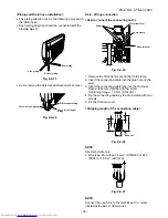
Page 66: ...r from the axis of the Front panel After that remove the Air inlet grille 6 Remove the Panel arms from the Front panel How to install the Air inlet grille 1 Insert three Panel arms on the Air inlet grille and fix each securely by screws 2 Set the Air inlet grille arm to the axis of the Front panel Refer to page 34 8 4 3 3 Insert the Grille stopper to the correct position and fix it securely with s...

Page 67: ...through the Front panel Remove the Drain band from the Front panel Cut away the Opening base for piping from Front panel and keep parts 3 Open 3 Cap screws and remove the screws 4 Remove 5 screws fixing the Front panel 5 Remove the hooks of the Panel LED nearly side from the Drain pan Front panel Continue Drain band Drain panel Cap screws Front Panel Screws ...

Page 68: ...t 3 Fix 5 hooks around the Front panel with conformation the Guide rib is inserting into the Back body 4 Fix 8 screws and close 3 Cap screws 5 Install the Drain band into the Front panel 6 Check the gap between the Front panel and the Back body 3 How to remove the Drain pan 1 Remove the Air inlet grille and the Front panel 1 2 2 Remove the Louver motor from the Drain pan 3 Remove the shaft of Hori...

Page 69: ... Remove the Electrical parts assembly NOTE When install the electrical parts assembly fix the screw after the Back body is fixed 5 How to remove the Refrigeration assembly 1 Remove the Air inlet grille the Front panel and the Drain pan assembly 1 2 3 2 Stop the gas at the Outdoor unit 3 Remove 2 pipes from the Refrigeration assembly 4 Remove the TC sensor from holder 5 Remove the pipe holder 6 Rem...

Page 70: ...tor 1 Remove the Air inlet grille and the Front panel 1 2 2 Disconnect 2 connectors 3 Remove the Fan covers 4 Remove the Motor band with holding the Fan motor and then remove the Fan motor with the Multi blade fans 5 Unfasten the Set screw and remove the Multi blade fans Refrigeration assembly Multiblade fan and Fan motor Fan cover Motor band Motor 2 Connectors Multi blade fan 2 Screws ...

Page 71: ... capacitor terminal 4 1 Unlatch the relay and pull it upward 2 Disconnect the lead wires from the relay terminal 5 1 Remove the transformer 2 screws 2 Disconnect the housing from the P C board 6 1 Disconnect the lead wires from the P C board 2 Remove the P C board after unhooking 4 clamps 7 1 Remove the spark killer 1 screw 2 Disconnect the lead wire from the terminal block 8 1 Remove the running ...

Page 72: ... 2 screws 2 Disconnect the lead wire from the terminal 5 1 Remove the transformer 2 screws 2 Disconnect the housing from the P C board 6 1 Disconnect the lead wire from the P C board 2 Remove the P C board after unhooking 4 clamps 7 1 Remove the spark killer 1 screw 2 Disconnect the lead wire from the terminal block 8 1 Remove the running capacitor with procedure 2 2 Remove the terminal cover of t...

Page 73: ...313 PC Board RAS 18UFHP ES 401 43T69314 PC Board RAS 18UFP ES 402 43T50004 Temperature sensor 403 43T60002 Terminal 404 43T62003 Cord clamp Location Part Description No No 405 43T69315 Display unit 406 43T50302 Temperature sensor 407 43T69311 PC Board RAS 24UFHP ES 407 43T69312 PC Board RAS 24UFP ES 407 43T69313 PC Board RAS 18UFHP ES 407 43T69314 PC Board RAS 18UFP ES 408 43T08349 Switch cover ...

Page 74: ...Body Assy Location Part Description No No 220 43T09314 Vertical Louver 221 43T49303 Pipe Holder 222 43T19304 Cover Body L 223 43T19305 Cover Body R 224 43T19306 Cover Body LD 225 43T19307 Bush Body R 226 43T19308 Bush Body D 227 43T82302 Installation Plate 228 43T60314 Terminal Cover 229 43T62303 Connector Cover 230 43T83003 Remote control Holder 231 43T69309 Wireless Remote control RAS 18UFHP ES ...

Page 75: ...Valve Packed 6 35Dia 18 43T47020 Bonnet 6 35Dia 19 43T46307 Valve Packed 12 7Dia 20 43T47018 Bonnet 12 7Dia Location Part Description No No 21 43T47308 Capillary Tube 1 0Dia 22 43T47014 Capillary Tube 1 7Dia 23 43T49011 Base Spring A 24 43T49012 Base Spring B 25 43T49019 Spring Buffer 26 43T55021 Capacitor 45MFD 420V 27 43T55007 Capacitor 2MFD 450V 28 43T60035 Terminal Block 4P 29 43T60014 Termina...

Page 76: ...6001 Bushing 15 43T43310 Condenser Assembly 16 43T43311 Sub Condenser Assembly 17 43T46308 Valve Packed 6 35Dia Location Part Description No No 18 43T47020 Bonnet 6 35Dia 19 43T46307 Valve Packed 12 7Dia 20 43T47018 Bonnet 12 7Dia 22 43T47014 Capillary Tube 1 7Dia 23 43T49011 Base Spring A 24 43T49012 Base Spring B 25 43T49019 Spring Buffer 26 43T55021 Capacitor 45MFD 420V 27 43T55007 Capacitor 2M...

Page 77: ...7 43T60036 Terminal Block 3P 30A 18 43T60037 Filter Clamp 19 43T41310 Compressor PA290X3F 4MS 20 13T62014 Protector Cord Location Part Description No No 21 43T62015 Protector Cord 22 43T49011 Base Spring A 23 43T49012 Base Spring B 24 43T49019 Spring Buffer 25 43T21306 Motor Fan AC 220 240V 50Hz 26 43T20010 Fan Propeller 490 27 43T96001 Bushing 28 43T96004 Bushing Cord 29 43T62013 Cover E Parts 30...

Page 78: ...lary Tube 2 0Dia 16 43T60035 Terminal Block 4P 17 43T60036 Terminal Block 3P 30A 18 43T60037 Filter Clamp Location Part Description No No 19 43T41310 Compressor PA290X3F 4MS 20 43T62014 Protector Cord 21 43T62015 Protector Cord 22 43T49011 Base Spring A 23 43T49012 Base Spring B 24 43T49019 Spring Buffer 25 43T21013 Motor Fan AC220 240V 50Hz 26 43T20010 Fan Propeller 490 27 43T96001 Bushing 28 43T...

Page 79: ...FILE NO SVM 02009 78 TOSHIBA CARRIER THAILAND CO LTD 144 9 MOO 5 BANGKADI INDUSTRIAL PARK TIVANON ROAD TAMBOL BANGKADI AMPHUR MUANG PATHUMTHANI 12000 THAILAND ...

Reviews: