background image

EN

ES

FR

IT

DE

PT

PL

CZ

RU

CR

HU

TR

NL

GR

SV

FI

NO

DK

RO

BG

EE

LV

SK

SI

3

To unit out line 

240mm

To unit out line 

35mm

To unit out line 

240mm

Of
fset 23mm from the right side edge is

the center of pipe hole

To unit out line 

120mm

0

23

35

120

180

240

Of

fset 85mm from the left side edge is

the center of pipe hole

1

7

40

50

170

132

23

170

85

Ø65 mm


45º

45º

75º

(Side view)

(Top view)

Indoor unit

Reception range

Remote control

Remote
control

Reception
range

Indoor unit

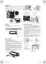
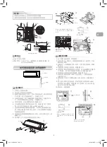
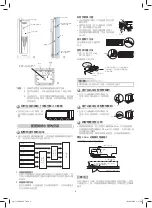
Wiring Connection

Wiring of the connecting cable can be carried out without removing the 
front panel.

1.  Remove the air inlet grille.
 

Open the air inlet grille upward and pull it toward you.

2.  Remove the terminal cover and cord clamp.
3.  Insert the connecting cable (according to the local rule) into the pipe hole 

on the wall.

4.  Take out the connecting cable through the cable slot on the rear panel so 

that it protrudes about 15 cm from the front.

5.  Insert the connecting cable fully into the terminal block and secure it tightly 

with screws.

6. Tighten 

fi

 rmly but not over 1.2 N·m (0.12 kgf·m)

7.  Secure the connecting cable with the cord clamp.
8.  Fix the terminal cover, rear plate bushing and air inlet grille on the indoor 

unit.


How to connect the connecting cable

INDOOR UNIT

INDOOR UNIT

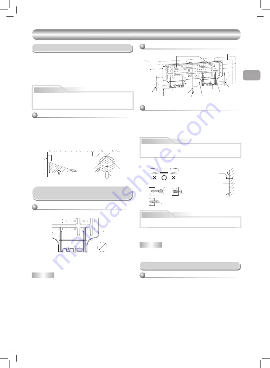
Installation Place

•  Direct sunlight to the indoor unit’s wireless receiver should be avoided.
•  The microprocessor in the indoor unit should not be too close to RF 

noise sources.

  (For details, see the owner’s manual.)  


Remote control

•  A place where there are no obstacles such as a curtain that may block the 

signal from the remote control.

•  Do not install the remote control in a place exposed to direct sunlight or 

close to a heating source such as a stove.

•  Keep the remote control at least 1 m apart from the nearest TV set or stereo 

equipment. (This is necessary to prevent image disturbances or noise 
interference.)

•  The location of the remote control should be determined as shown below.

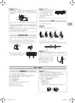
Cutting a Hole and Mounting

Installation Plate


NOTE

•  When drilling a wall that contains a metal lath, wire lath or metal plate, be 

sure to use a pipe hole brim ring sold separately.


Cutting a hole

When installing the refrigerant pipes from the rear


Mounting the installation plate

When the installation plate is directly mounted 
on the wall

1. Securely 

fi

 t the installation plate onto the wall by screwing it in the upper 

and lower parts to hook up the indoor unit.

2.  To mount the installation plate on a concrete wall with anchor bolts, use the 

anchor bolt holes as illustrated in the below 

fi

 gure.

3.  Install the installation plate horizontally in the wall.

When installing the installation plate with a mounting screw, do not use 
the anchor bolt holes. Otherwise, the unit may fall down and result in 
personal injury and property damage.  

1.  After determining the pipe hole position on the mounting plate (

), drill the 

pipe hole (Ø65 mm) at a slight downward slant to the outdoor side. 

•  A place which provides the spaces around the indoor unit as shown in the 

diagram

•  A place where there are no obstacles near the air inlet and outlet
•  A place which allows easy installation of the piping to the outdoor unit
•  A place which allows the front panel to be opened
•  The indoor unit shall be installed as top of the indoor unit comes to at 

least 2 m height. Also, it must be avoided to put anything on the top of the 
indoor unit.  

CAUTION

CAUTION

Failure to 

fi

 rmly install the unit may result in personal injury and property 

damage if the unit falls.

•  In case of block, brick, concrete or similar type walls, make 5 mm dia. holes 

in the wall.

•  Insert clip anchors for appropriate mounting screws 

7

.


NOTE

•  Secure four corners and lower parts of the installation plate with 4 to 6 

mounting screws to install it.

7

CAUTION

m from the right side edge is

e

 center of pipe hole

35

120

180

240

The center of the pipe hole is 
above the arrow.

Pipe hole

23 mm

Ø65 mm

Installation plate
(Keep horizontal direction.)

5 mm dia. hole

Mounting screw
Ø4 x 25

R

Clip anchor
(local parts)

Anchor bolt

Projection
15 mm or less

Anchor bolt holes

Hook

Hook

Hook

Pipe hole

Pipe hole (Ø65 mm)

Installation plate

Weight

Indoor unit

Thread

2 m or more from 

fl

 oor

Mounting 
Screw

01_1115551256-EN.indd   3

01_1115551256-EN.indd   3

8/26/2558 BE   2:50 PM

8/26/2558 BE   2:50 PM

Summary of Contents for RAS-24BAS-HK

Page 1: ...ONDITIONER SPLIT TYPE INSTALLATION MANUAL Indoor unit RAS 24 30BKS HK Outdoor unit RAS 24 30BAS HK 1115551256 ENGLISH 01_1115551256 EN indd 1 01_1115551256 EN indd 1 8 26 2558 BE 2 50 PM 8 26 2558 BE 2 50 PM ...

Page 2: ...DOOR UNIT 6 Installation Place 6 Refrigerant Piping Connection 7 Evacuating 7 Wiring Connection 7 Electrical Work 8 Refrigerant Piping 8 OTHERS 9 Gas Leak Test 9 Remote Control A B Selection 9 Test Operation 9 Auto Restart Setting 9 CONTENTS EN 安全預防措施 1 室內與室外機組的安裝圖 2 選購性安裝零部件 2 室內機組 3 安裝地點 3 鑽孔及安置安裝板 3 線路連接 3 如何連接遙控器為有線操作 4 配管與排水管的安裝 5 固定室內機組 6 排水 6 室外機組 6 安裝地點 6 冷凍管連接 7 排空 7 線路連接 7 電氣工作 8 冷凍劑管 8 ...

Page 3: ...S FAILURE TO FOLLOW THIS INSTRUCTION CAN RESULT IN FIRE OR EXPLOSION TO PREVENT OVERHEATING THE INDOOR UNIT AND CAUSING A FIRE HAZARD PLACE THE UNIT WELL AWAY MORE THAN 2 M FROM HEAT SOURCES SUCH AS RADIATORS HEATERS FURNACE STOVES ETC WHEN MOVING THE AIR CONDITIONER FOR INSTALLING IT IN ANOTHER PLACE AGAIN BE VERY CAREFUL NOT TO GET THE SPECIFIED REFRIGERANT R410A WITH ANY OTHER GASEOUS BODY INTO...

Page 4: ...ote control Saddle Extension drain hose Not available provided by installer Shield pipe Attach to the front panel Air filter Installation plate 50 mm or more 170 mm or more 170 mm or more 150 mm or more 1000 mm or more 600 mm or more 6 5 Filter Filter Hook Hook 500 mm or more Remark Detail of accessory and installation parts can see in the accessory sheet Some pictures might be different from the ...

Page 5: ...ontains a metal lath wire lath or metal plate be sure to use a pipe hole brim ring sold separately Cutting a hole When installing the refrigerant pipes from the rear Mounting the installation plate When the installation plate is directly mounted on the wall 1 Securely fit the installation plate onto the wall by screwing it in the upper and lower parts to hook up the indoor unit 2 To mount the inst...

Page 6: ...ote Controller for Wire Operation For indoor unit Air inlet grille Front panel 1 Display board 2 3 Display unit Remove screw 1 Remove cover of remote controller by sliding down and take it out 2 If batteries are exist please take them out The combination of using wire controller and batteries may cause of batteries explosion 3 Make hole for insert control wire by use screwdriver break the polyeste...

Page 7: ...e the wall surface If the connecting pipe is laid exceeding 43 mm above the wall surface the indoor unit may unstably be set on the wall When bending the connecting pipe make sure to use a spring bender so as not to crush the pipe Bend the connecting pipe within a radius of 30 mm To connect the pipe after installation of the unit figure How to install the air inlet grille on the indoor unit When a...

Page 8: ...vel is up to 10 m A place where the drain water does not cause any problems CAUTION 1 Install the outdoor unit in a location where there are no obstructions near its air intake or air outlet 2 When the outdoor unit is installed in a place that is always exposed to strong winds like on the coast or on a high story of a building secure the normal fan operation using a duct or a wind shield 3 Especia...

Page 9: ...hose For R410A only Connecting pipe 101 kPa 76 cmHg KEEP IMPORTANT 5 POINTS FOR PIPING WORK 1 Take away dust and moisture inside of the connecting pipes 2 Tighten the connections between pipes and unit 3 Evacuate the air in the connecting pipes using a VACUUM PUMP 4 Check gas leak connected points 5 Be sure to fully open the packed valves before operation CAUTION Wiring Connection 1 Remove the val...

Page 10: ... L 60 60 1 Connecting cable Terminal screw Screw Terminal block Earth line Earth line Connecting cable Power supply cord Power supply cord Cord clamp Cord clamp Round type terminal Round type terminal Cable tie Power supply cord Connecting cable Protective bush Knockout procedure Rear direction Pipe cover PLATE TRANSPORTATION Should be take off and no need to fix The indoor outdoor connecting pipe...

Page 11: ...ration can be preserved by setting either one remote control to B setting Both are set to A setting in factory shipment The remote control signal is not received when the settings of indoor unit and remote control are different There is no relation between A setting B setting and A room B room when connecting the piping and cables This product is designed so that after a power failure it can resta...

Page 12: ...人傷害 在用手觸摸具有鋒利邊緣的部件時請當心 y 在安裝本機之前 請仔細閱讀本手冊 它含有正確安裝本機的重要說明 y 製造商對於未依照本手冊說明所致之損壞 不承擔任何責任 通知您當地電力供應者的要求 在安裝之前 請務必通知當地電力供應商有關空調安裝事宜 若您遇到任何問題 或電力供應商不同意安裝 則我們的服務代理商會 採取妥善的相應措施 新型冷凍劑空調器的安裝 注 意 y 本空調器採用新型 HFC 冷凍劑 R410A 該冷凍劑不會損耗臭氧層 由於 R410A 冷凍劑的壓力約為 R22 冷凍劑的 1 6 倍 因此很容易受到水 氧化膜和油等雜質的影響 也由於採用了此新型冷凍劑 冷 凍機油也需要改變 因此 在安裝作業中 應確保水 灰塵 原來的冷凍劑或冷凍機油不能進入新型冷凍劑空調器的冷凍循環中 為避免冷凍劑與冷凍機油混合 主機上連接部分的加注口尺寸與常規冷凍劑的加注口尺寸不同 需要不同尺寸的工具 ...

Page 13: ...的安裝圖 室內與室外機組的安裝圖 y 若本機可能暴露在強風中 請用固定螺栓與螺母穩固室外機 組 y 請使用 Ø8 mm 或 Ø10 mm 錨狀螺栓與螺母 室外機組的固定螺栓布置 2 3 8 4 1 電池 平頭木螺釘 遙控器支座 進行完排水測試後 用 纖維尼龍膠帶來包裹 無線遙控器 管子夾頭 延長排水管 無 由安裝人員提供 遮護管 安置於前面板 空氣過濾器 安裝板 50 mm 或以上 170 mm 或以上 170 mm 或以上 150 mm 或以上 1000 mm 或以上 600 mm 或以上 6 5 過濾器 過濾器 掛鉤 掛鉤 500 mm 或以上 註解 y 附件和安裝零部件的詳情 可參閱附件單 y 有些圖片可能會與實物不同 提供無線型遙控器 同時也可作為有線 型使用 如需進行有線控制 請參見 如何連接 遙控器為有線操作 8 平頭木螺釘 平頭木螺釘 電池蓋 600 mm 150 mm 15...

Page 14: ...於直射陽光或靠近諸如暖爐等 熱源之處 y 將遙控器放置於離電視機或立體聲設備至少 1 m 之處 這是 必要的 以避免影像受到干擾和產生噪音 y 如圖所示決定遙控器的位置 注 意 y 應避免陽光直接照射到室內機組的無線接收器 y 室內機的微處理機不可太靠近 RF 噪音源 欲獲取詳情 請參閱使用說明書 側視 俯視 室內機組 接 收 範 圍 遙控器 遙控器 接收範圍 室內機組 鑽孔 當從背面安裝冷凍劑配管時 鑽孔及安置安裝板 備注 y 在含有金屬條 電線條或金屬板的牆上鑽孔時 務必用各別銷售 的管孔環圈 1 決定了安裝板 上的管孔位置後 在稍微向下傾斜至室外 機一側之處鑽孔 Ø65 mm 當直接安裝安裝板到牆上時 1 通過用螺絲釘住上面和下面的部份來將安裝板牢牢圍住在牆 上以掛鉤住室內機組 2 若要在混凝土牆上用錨狀螺栓固定安裝板 請使用下圖中所 示的錨栓孔 3 將安裝板打橫式安裝於牆上 注 意...

Page 15: ...向上的進氣格柵 2 安全取下前面板的四個螺絲 3 輕輕打開前面板的下部分 然後將前面板的上部分朝著您的 方向拉動 把它從後面板卸下 如圖 1 所示 4 拆卸前面板後 取下本機的螺釘和顯示單元 如圖 2 所 示 然後打開顯示單元的前蓋 如圖 3 所示 5 排列控制線 詳細步驟和說明如圖 4 所示 6 安全連接控制線至顯示單元板終端 如圖 5 所示 請加 緊 但力矩不要超過 0 12 N m 0 01 kgf m 7 將控制線貫穿顯示裝置前蓋凹槽 然後用主殼重組顯示裝 置 即進行圖 2 和 3 的逆過程 注意不要讓顯示裝置前 後蓋壓迫控制線 8 將控制線在電源連接電纜的相同部分 從室內單元拉出 如 圖 6 所示 9 按步驟 1 至 3 的逆反過程重組室內單元 室內單元 如何連接遙控器為有線操作 1 向下滑動遙控器蓋 將其揭開 2 如果有電池 請取出 線路控制器和電池一起使用 可能 導致電池爆炸...

Page 16: ... 左底連接和左後連接的配管 必須改變排水 管方向和排水蓋位置 右後 左後 左底 左 右底 右 切割前 面板裂口 改變排 水管方向 準備配管 如何移開排水管 y 可以通過擰下螺釘 然後扭轉和拉來移 開排水管 y 移開排水管時 要小心鋼板的任何銳 邊 這些銳邊可引起受傷 y 要安裝排水管 請將其穩固穩固插入 直到連接件觸到隔熱體 然後用原有螺 絲上緊 排水蓋取下方法 用尖頭鉗夾住排水蓋將其 拉出 固定排水蓋方法 1 將六角扳手 4 mm 插入頂端中心 2 穩固插入排水蓋 在插入排水蓋時 切勿塗抹潤滑油 冷凍機油 否則會造成插頭老化 和排水滲漏 插入六角形扳手 4 mm 無間隙 穩固地插入排水管和排水蓋 否則會產生漏水 進行在右或左配管安裝時 y 在用小刀或斷離針將裂口劃破後 再用一對剪鉗或類似工具將其剪 下 進行右底或左底配管安裝時 y 在用小刀或斷離針將裂口劃破後 再用一對剪鉗或類似工具將其...

Page 17: ... 若是 進行向左配管及左後配管安裝時 請用膠紙只是將輔助配 管捆起來 室內機組 連接電纜 輔助管 安裝板 y 請小心處理配管 以便沒有任何配管自室內機的後面板伸 出 y 請仔細連接輔助管與連接管並切斷纏繞在連接管上的絕熱 帶以避免連接處的重復卷縛 此外 請用乙烯樹脂帶密封 連接處 y 因為結露將導致機器出毛病 請確定已對兩所連接的管道 隔熱 請使用聚乙烯泡沫作為隔熱材料 y 在彎曲管子時 請當心不要壓壞它 y 要從安裝板上拆下室內機時 請在 所指定的部件處向上推起室內機的 底部 然後朝您的方向拉出即可 固定室內機組 1 將管子穿過牆上的洞並讓室內機組掛鉤住安裝板稍高處的掛 鉤 2 向左和右擺筋室內機組以確它已牢固地掛鉤在安裝板上 3 將室內機組壓向牆面以讓它掛鉤住安裝板的較低部份 向您 所在方向拉動本機以確定它已牢因地掛鉤在安裝板上 1 2 1 掛在此 安裝板 掛鉤 按 從掛鉤上取下 推 ...

Page 18: ...徑 緊固扭矩 Ø6 35 mm 16 至 18 1 6 至 1 8 kgf m Ø15 88 mm 65 至 80 6 5 至 8 0 kgf m 注 意 y 進行管道工作時請嚴守以下 5 項要點 1 清除灰塵和濕氣 連接管內側 2 緊固連接 管與本機之間 3 使用真空泵抽空連接管內的空氣 4 檢查氣體是否泄漏 連接點 5 操作前請確保完全打開壓縮閥 請務必使用具有防逆流功能的真空泵以防止泵內的油在泵停止 工作後流回空調器的管子中 如果真空泵內的油進入了使用 R410A 冷凍劑的空調器 則 冷凍循環可能產生故障 1 將充氣管從岐管表連接到氣體側壓縮閥的維修槽上 2 連接充氣管到真空泵的槽口上 3 完全打開岐管表閥的低壓側把手 4 操作真空泵以開始排空 若管的長度為 20 m 請進行排空 約 15 分鐘 20 m 採用 15 分鐘 假設泵的容量為每分鐘 27 升 然後確認復合壓力表的讀數為 ...

Page 19: ...附保護襯套和防護材料安裝在通道孔周圍 以保護電線 和管道 務必在連接管道後安裝管蓋 切開管蓋下方的狹縫 促進安裝的進行 連接管道後 務必安裝管蓋 透過切斷管蓋下部的狹縫 可輕鬆安裝管蓋 隨附保護襯套 隨附通道孔防護材料 牢固地安裝防護材料 以免 鬆動 型號 RAS 24BKS HK RAS 30BKS HK 電源 50Hz 220V 單相 最大運行電流 13A 21A 電源插座及保險絲額定 16A 27A 電源線 4 mm2 H07RN F 或 60245 IEC66 或 3 5 mm2 AWG 12 備注 連接電纜 y 電線類型 1 5 mm2 以上 H07RN F 或 60245 IEC66 或 1 3 mm2 AWG 16 注 意 y 錯誤的線路連接可能會導致電氣部件燒壞 y 從室外機組運行線路到室內機組 電纜尺寸及連接方式等 時務必遵守當地法規 y 每條電線都必須牢固地連接 y 如...

Page 20: ...不相同時 遙控器訊號將不被接收 y 連接管道和電纜線時 A 設定值 B 設定值和 A 房間 B 房 間之間是沒有關係的 在 2 個空調器安裝得比較近的情況下對每個室內機分別使用 遙控器 此產品有在電源中斷並恢復電供後 自動重新 動 電流中斷 前的操作模式之設計 1 2 檢測操作 要轉換 TEST RUN COOL 模式時 按 RESET 重置 鍵 10 秒 鐘即可 嗶嗶機將發出短嗶聲 RESET 鍵 y 請用檢漏儀或肥皂水檢查擴口螺母連接 閥心蓋連接和維修 口蓋連接以防止漏氣 擴口螺母連接 室內機組 擴口螺母連接 室外機組 閥心蓋連接 維修口蓋連接 信 息 此產品的自動重新 動功能在出廠前已被設置 關閉位 置 需要時可將它打開 如何設定自動重新啟動 1 按住室內機組上的 RESET 按鈕 3 秒種來設定操作 3 聲嗶 聲且 OPERATION 燈閃爍 5 秒種 1 秒閃爍 5 次 2 按住...

Page 21: ...MEMO 02_1115551256 CT indd 10 02_1115551256 CT indd 10 10 1 2558 BE 3 01 PM 10 1 2558 BE 3 01 PM ...

Page 22: ...MEMO 02_1115551256 CT indd 11 02_1115551256 CT indd 11 10 1 2558 BE 3 01 PM 10 1 2558 BE 3 01 PM ...

Page 23: ...02_1115551256 CT indd 12 02_1115551256 CT indd 12 10 1 2558 BE 3 01 PM 10 1 2558 BE 3 01 PM ...

Page 24: ...1115551256 02_1115551256 CT indd 13 02_1115551256 CT indd 13 10 1 2558 BE 3 01 PM 10 1 2558 BE 3 01 PM ...

Reviews: