background image

Toshiba 1115551210 (COVER)

1115551210

TSB 1115551210_EN.indb   21

TSB 1115551210_EN.indb   21

6/18/14   9:03 AM

6/18/14   9:03 AM

Summary of Contents for RAS-24N3AV Series

Page 1: ...10 COVER Indoor unit RAS 24N3KV Series Outdoor unit RAS 24N3AV Series AIR CONDITIONER SPLIT TYPE INSTALLATION MANUAL 1115551210 ENGLISH TSB 1115551210_EN indb 1 TSB 1115551210_EN indb 1 6 18 14 9 02 AM 6 18 14 9 02 AM ...

Page 2: ...stallation 6 Indoor Unit Fixing 7 Drainage 7 OUTDOOR UNIT 7 Accessory Parts 7 Installation Place 8 Refrigerant Piping 9 Refrigerant Piping Connection 9 Evacuating 10 Wiring Connection 11 Electrical Work 11 Earthing 12 Finishing 12 Test Run 12 Annual Maintenance 12 Functions to be Implemented Locally 12 Troubleshooting 13 Appendix 15 OTHERS 17 Remote Control A B Selection 17 Test Operation 17 Auto ...

Page 3: ...a result of improper installation Specified tools and pipe parts for model R410A are required and installation work must be done in accordance with the manual HFC type refrigerant R410A has 1 6 times more pressure than that of conventional refrigerant R22 Use the specified pipe parts and ensure correct installation otherwise damage and or injury may be caused At the same time water leakage electri...

Page 4: ...t may crack after a long period of usage and it may cause the leakage of refrigerant Wear gloves heavy gloves such as cotton gloves for installation work Failure to do so may cause personal injury when handling parts with sharp edges Do not touch the air intake section or the aluminum fins of the outdoor unit It may cause injury Do not install the outdoor unit in a place which can be a nest for sm...

Page 5: ... between the indoor unit and wall and tilt the indoor unit for better operation Do not allow the drain hose to get slack Make sure to run the drain hose sloped downward The auxiliary piping can be connected to the left rear left rear right right bottom right or bottom left Left Bottom right Right Rear left Rear right Bottom left Insulate the refrigerant pipes separately with insulation not togethe...

Page 6: ...l the pipe hole 65 mm at a slight downward slant to the outdoor side When the installation plate is directly mounted on the wall 1 Securely fit the installation plate onto the wall by screwing it in the upper and lower parts to hook up the indoor unit 2 To mount the installation plate on a concrete wall with anchor bolts use the anchor bolt holes as illustrated in the below figure 3 Install the in...

Page 7: ... not over 0 12 N m 0 01 kgf m For remote controller 1 Remove cover of remote controller by sliding down and take it out 2 If batteries are exist please take them out The combination of using wire controller and batteries may cause of batteries explosion 3 Make hole for insert control wire by use screwdriver break the polyester sheet as shown on figure 7 4 Insert control wire from rear side of remo...

Page 8: ...nt panel slit Cut out the slit on the leftward or right side of the front panel for the left or right connection and the slit on the bottom left or right side of the front panel for the bottom left or right connection with a pair of nippers 2 Changing drain hose For leftward connection bottom leftward connection and rear leftward connection s piping it is necessary to change the drain hose and dra...

Page 9: ...t it is firmly hooked up on the installation plate 3 While pressing the indoor unit onto the wall hook it at the lower part on the installation plate Pull the indoor unit toward you to confirm that it is firmly hooked up on the installation plate OUTDOOR UNIT OUTDOOR UNIT Hook here Hook Press unhook Push Push NOTE If the pipe is bent incorrectly the indoor unit may unstably be set on the wall Afte...

Page 10: ...the wind direction When using an air conditioner under low outside temperature conditions Outside temp 5 C or lower in COOL mode prepare a duct or wind shield so that it is not affected by the wind Example 500 mm Strong wind Strong wind Wind shield Wind shield As shown in the figure below install the foundation and vibration proof rubber pads to directly support the bottom surface of the fixing le...

Page 11: ...or outdoor connecting pipes can be connected in 4 directions Take off the knockout part of the pipe cover through which pipes or wires will pass through the base plate Detach the pipe cover and tap on the knockout section a few times with the shank of a screwdriver A knockout hole can easily be punched After punching out the knockout hole remove burrs from the hole and then install the supplied pr...

Page 12: ...se not only a gas leak but also trouble with the refrigeration cycle Do not apply refrigerant oil to the flared surface Unit N m Outer dia of copper pipe Tightening torque 9 52 mm 33 to 42 3 3 to 4 2 kgf m 15 88 mm 68 to 82 6 8 to 8 2 kgf m CAUTION 1 Do not put the crescent wrench on the cap or cover The valve may break 2 If applying excessive torque the nut may break according to some installatio...

Page 13: ...r supply 220 240 V 50Hz Maximum running current 20A Installation fuse rating 25 A all types can be used Power wire H07RN F or 60245 IEC66 3 5 mm2 or more Indoor outdoor connecting wires H07RN F or 60245 IEC66 1 5 mm2 or more How to wire 1 Connect the connecting wire to the terminal as identified with their respective numbers on the terminal block of the indoor and outdoor units H07RN F or 60245 IE...

Page 14: ...mpressor during startup To protect the compressor power is supplied from the 220 240 VAC input to the unit to preheat the compressor Check the following before starting a test run That all pipes are connected securely without leaks That the valve is open If the compressor is operated with the valve closed the outdoor unit will become overpressurized which may damage the compressor or other compone...

Page 15: ...peration select switch SW804 Existing pipe switch SW802 P C board Troubleshooting You can perform fault diagnosis of the outdoor unit with the LEDs on the P C board of the outdoor unit in addition to using the check codes displayed on the wired remote controller of the indoor unit Use the LEDs and check codes for various checks Details of the check codes displayed on the wired remote controller of...

Page 16: ... on the service P C board 15 MCU MCU communication error 16 Discharge temperature error 17 Abnormal power open phase detected or abnormal voltage 18 Heat sink overheat 19 Gas leak detected 20 4 way valve reverse error 21 High pressure release operation 22 Outdoor fan motor error 23 Compressor driver short circuit protection 24 Position detection circuit error in one line display The LEDs and DIP s...

Page 17: ...e is the possibility that copper green rust has been generated 6 When the existing air conditioner is removed after refrigerant has been recovered Check if the oil is judged to be clearly different from normal oil The refrigerator oil is copper rust green in color There is the possibility that moisture has mixed with the oil and rust has been generated inside the pipe There is discolored oil a lar...

Page 18: ...to 5 HP gas pipe size is 15 9 mm t Turn the existing pipe switch on the cycle control PC board of the outdoor unit to ON side At shipment from factory OFF t ON for existing pipe Refer to the table below Be sure to set the contents in the table below in order to restrict the refrigerating cycle pressure of the equipment in the pipe standard Existing pipe SW Switch 3 HP Bit 3 of SW802 t ON Airtight ...

Page 19: ...eceive the remote control signal simultaneously and operate In this case the operation can be preserved by setting either one remote control to B setting Both are set to A setting in factory shipment The remote control signal is not received when the settings of indoor unit and remote control are different There is no relation between A setting B setting and A room B room when connecting the pipin...

Page 20: ...毒氣體的產 警告 決不可移除本機的任何安全防護裝置或忽視任何的安全組合開關等以變更本機 必須請銷售商或專業供應商進 安裝 作 安裝可能會由於安裝不正確造成漏 電擊或 災 需要使 R410A 型號的指定 具和配管部件 並根據本 冊進 安裝 作 HFC 型冷凍劑 R410A 的壓 傳統冷凍劑 R22 多 1 6 倍 使 指定的 配管部件 確保正確安裝 否則可能會造成財物損失和 或個 傷害 同時 可能會發 漏 電擊和 災 務必將本機安裝在可承受其重量的地 如果本機安裝處的載重量不夠 或是本機未正確安裝 本機可能會掉落 造成個 傷害 必須由合資格的電氣 程師根據安裝 作相關法規 內部配線規定和本 冊執 電氣 作 必須使 專 電路和額定電壓 電 不 或安裝不正確可能 會造成電擊或 災 使 卡胎電纜連接室內機 室外機的電線 不可進 中間連接 絞線和單線連接 連接或固定不正確可能會造成 災 室內機和室外...

Page 21: ...置排 管 使本機正確排 確保廢 正確排放 排 不當可能會導致漏 造成傢俱泡 依照指定的 法 使 扭矩扳 旋緊錐形螺帽 請勿使 過 的扭矩 否則 經過 時間使 後 螺帽可能會破裂 造成冷凍劑洩漏 進 安裝 作時 請配戴 套 厚 套 如棉質 套 否則 使 銳利邊緣的部件時 可能會造成個 傷害 請勿觸摸室外機的進氣部分或鋁 可能造成個 傷害 請勿將室外機安裝在可能有 動物居住的地 動物可能會進 並接觸內部電氣部件 造成故障或 災 請使 者維護本機週遭環境的整潔 安裝 作完成後 務必嘗試運作 並根據 冊向顧客說明如何使 與維護本機 請顧客將操作 冊與安裝 冊放在 起 製造商對於未依照本 冊說明所致之損壞 不承擔任何責任 通知您當地電 供應者的要求 在安裝之前 請務必通知當地電 供應商有關空調安裝事宜 若您遇到任何問題 或電 供應商不同意安裝 則我們的服務代理商會採取妥善的相應措施 Toshiba ...

Page 22: ...內與室外機組的安裝圖 室內與室外機組的安裝圖 部件 編號 部件名稱 數量 致冷管 液體側 9 52 mm 氣體側 15 88 mm 各 個 配管絕熱材料 聚 烯泡沫 8 mm 厚 1 油灰 PVC 帶 各 個 選購性安裝零部件 若本機可能暴露在強 中 請 固定螺栓與螺 穩固室外機組 請使 直徑 10 mm 錨狀螺栓與螺 室外機組的固定螺栓布置 短管安裝孔 排 孔 排 孔 輔助管可連接在左 左後 右後 右 右底或左底部位 左 右底 右 左後 右後 左底 絕緣材料分別地為冷凍劑配管 絕緣 起進 8 mm 厚耐熱聚 烯泡沫 㐖拟 進 完排 測試後 烯樹脂帶來包 裹 管 夾頭 延 排 管 無 由安裝 員 提供 200 mm 或以上 150 mm 或以上 1000 m m 或 以 上 500 mm 或以上 600 mm 或以上 備註 附件和安裝零部件的詳情 可參閱附件單 些圖 可能與實際零部件有所不...

Page 23: ...牢牢圍住在牆上以掛鉤住室 內機組 2 若要在混凝 牆上 錨狀螺栓固定安裝板 請使 下圖中所 的錨栓孔 3 將安裝板打橫式安裝於牆上 若是 磚塊 混凝 或類似牆壁類型 請在牆壁上鑽 5 mm 直徑的孔 插 夾鉗錨於適當的安置螺釘 g 安裝板的安置 備註 4 到 6 枚安置螺絲緊固 4 邊 和較低部份以安裝安裝板 5 mm 直徑孔 安裝板 保持 平 向 夾鉗錨 當地部件 錨狀螺栓 凸出 15 mm 或更少 g 安置螺釘 4 x 25 注意 若沒有穩固安裝本機 本機落下時可能導致個 傷害和財物損失 注意 當 安置螺釘來安裝安裝板時 切勿 錨狀螺栓孔 否則 本機可能摔落 致傷 或造成財物損失 To unit out line 240mm To unit out line 35mm To unit out line 240mm Offset 23mm from the right side edge...

Page 24: ...Ẉ帀惉 0 12 N m 0 01 kgf m 蒦δ 遙控器 1 Ẇ㽌 惔㐢 商δ 2 㠗㞄杶㳛蒩孆 δⲂ㞄乕㐢 劂杶㳛ṻ已Ὼ䖣 典㝾悛 杶㳛䊁 䄳δ 3 䖣堵 已 僕懪䋂ẅ擸 蒩ὠ 㑍 㐢 乕蒩 g 䦵δ 4 惔㐢 兇柝㑍 㐢 乕蒩 h 䦵δ 5 Ὼ䖣㑋 䛿堵打蒩Ⲃ i j 懈俩䛿㐢 乕 Ⱅ 䭪 ẅ蒥搑久蒩 䡤Ẉ帀惉 0 25 N m 0 03 kgf m 蒦δ 6 Ⲃ㐢 乕䫺惉惔㐢 兇柝䛿㼘㩸蒩 k 䦵δ 7 Ⲃ㑋 䛿堵打 3 1 x 16L Ⱅ 䋁ẅ蒩ὠ 㐖惔㐢 蒩 l 䦵δ 8 㪔媓ạ懈俩Ⰴ奘 蒩ὠ ⰕẆ㘴堵打 3 1 x 25L 蒩 l 䦵δ 9 䶿奘懈ά夆朣暿䛿杶㳛商蒩䆱〇䖣㑋 䛿堵打 3 1 x 25L Ⲃ杶㳛商悞 惔㐢 Ⱅ 䋁ẅ蒩 m 䦵蒥搑久蒩 䡤Ẉ帀惉 0 15 N m 0 02 kgf m 蒦δ 10 扈㘫䶿奘惔㐢 商δ 7 Ⲃ㐢 乕䫺惉棪䦵 商㩸蒩䆱〇 㕈ῗ b c...

Page 25: ... 排 管和排 蓋 否則會產 漏 將配管連接 左側 請彎曲連接配管 使它安置於離牆 43 mm 以內的範圍內 若連接配管 被置於離牆表 43 mm 以上的範圍 安置於牆上的室內機可能不穩固 彎曲連接配管時 請使 彈簧彎管器 以防損壞連接配管 應在 30 mm 的範圍內彎曲管 安裝機體之後連接管 圖 插 六 扳 4 mm 如何在室內機組上安裝空氣 格柵 當安裝空氣 格柵時 應進 與取出格柵時相反的步驟 配管與排 管的安裝 由於冷凝 會導致機械故障 必須保證兩種連接配管絕熱良好 使 聚 烯泡沫作為絕熱材料 配管和排 管的組成 右後 左後 左底 左 右底 右 切割前 板裂 改變排 管 向 準備配管 80 液體側 氣體側 520 mm 420 mm 擴 的最前 室內機組的外形 R 30 mm 寶麗森 聚 烯 芯或 類似物來彎曲配管 螺絲起 的把 等 43 mm 備註 1 寫Ὼ䖣杔 乞ⲉ乕蒩ὠ 悞㐠惔...

Page 26: ...件處向上推起室內機的底部 然 後朝您的 向拉出即可 1 將管 穿過牆上的洞並讓室內機組掛鉤住安裝板稍 處的掛鉤 2 向左和右擺筋室內機組以確定它已牢固地掛鉤在安裝板上 3 將室內機組壓向牆 以讓它掛鉤住安裝板的較低部份 向您所在 向拉動 本機以確定它已牢固地掛鉤在安裝板上 室外機組 室外機組 挂在此 掛鉤 按 從掛鉤上取下 推 推 備註 若管 彎曲不正確 室內機組可能無法穩固安裝於牆上 將管 通過管孔之後 將連接管連接 輔助管並 膠紙將它們纏繞起來 注意 請 膠紙緊緊地把輔助管 2 和連接電纜捆綁起來 若是進 向左配管 及左後配管安裝時 請 膠紙只是將輔助配管 2 捆起來 請 處理配管 以便沒有任何配管 室內機的後 板伸 請仔細連接輔助管與連接管並切斷纏繞在連接管上的絕熱帶以避免連接 處的重復卷縛 此外 請 烯樹脂帶密封連接處 由於冷凝 會導致機械故障 必須保證兩種連接配管絕熱良好 使 聚...

Page 27: ...1 將本機安裝在其排氣 對建築物牆壁的位置 使本機與牆 之間的距離保持 500 mm 或以上 在 外低溫條件下 外溫度 5 C 或以下 使 空調機的 COOL 模 式時 準備 管或擋 罩 以免空調機受到 的影響 例 2 考慮空調機運轉季節的 向 安裝本機時將排氣 與 向呈直 500 mm 強 強 擋 罩 擋 罩 如下圖所 安裝基底與防震橡膠墊以直接 撐接觸室外機組底板下 的固 定腳座底 為配管朝下的室外機組安裝基底時 考慮配管 作 若要從排 管排 請安裝以下短管和防 橡膠蓋 並使 市售的排 管 內徑 16 mm 另外 矽膠等材料封住螺絲 以防 漏 有些情況可能會造成結露或滴 若要將廢 起排光 使 排 盤 正確 正確 不正確 固定腳座 基底 基底 防震橡膠墊可吸震 室外機組底板 撐接觸室外機組底板下 的固定腳座底 使錨栓凸出 15 mm 或更少 如果只 撐固定腳座的 端點 可能會變形 不要只...

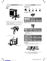
Page 28: ... 扳 擰緊 閃爍的 外張的 1 切管器切割管 管蓋穿孔 穿孔程序 傾斜 粗糙 彎曲 配管 膜 半聯合或迫緊閥 使 扳 緊固 擴 螺 使 扭矩扳 旋緊 內部螺紋側 外部螺紋側 可以在 4 個 向連接室內 室外連接配管 取下配管或電線將穿過底板的管 蓋穿孔部分 拆卸管蓋 然後 螺絲起 柄輕擊穿孔部分數次 可以輕鬆打出穿孔 打出穿孔後 清除洞孔周圍的 邊 然後在通道孔周圍安裝隨附保護襯套 和防護材料 以保護電線和配管 務必在連接配管後安裝管蓋 切開管蓋下 的狹縫 以便安裝 連接配管後 務必安裝管蓋 切開管蓋下部的狹縫 以便輕鬆安裝管蓋 後 管蓋 側 前 下 作時 請配戴厚 作 套 隨附保護襯套 隨附通道孔防護材料 牢固地安裝防護材料 以免鬆動 A 2 如圖所 務必 兩個扳 旋鬆或旋緊氣體側閥的擴 螺帽 如果您使 個活動扳 擴 螺帽無法旋緊 所需的鎖緊扭矩 另 個活動扳 旋鬆或旋緊液體側閥的擴 螺...

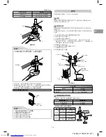
Page 29: ... 33 42 3 3 4 2 kgf m 15 88 mm 68 82 6 8 8 2 kgf m 蓋 管閥 保護蓋 旋緊 旋鬆 擴 螺 氣體側閥 注意 1 請勿將活動扳 放在保護蓋或蓋 上 可能會損壞閥 2 如果扭矩過 在某些安裝情況下 螺帽可能會損壞 不正確 蓋 保護蓋 壓 表 壓 計歧管閥 101 kPa 76 cmHg 低壓側把 復合壓 表 真空泵 壓側把 保持完全關閉 充氣管 僅適 於 R410A 於防逆流的 真空泵適配器 僅適 於 R410A 氣體側的壓縮閥 充氣管 僅適 於 R410A 充氣 閥 調節針 添加冷凍劑 冷凍劑 24 Class 冷凍劑填充 於 20 m 冷凍劑填充 21 30 m 30g m 注意 進 管道 作時請嚴守以下 5 項要點 1 清除灰塵和濕氣 連接管內側 2 緊固連接 管與本機之間 3 使 真空泵抽空連接管內的空氣 4 檢查氣體是否泄漏 連接點 5 ...

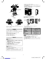
Page 30: ... 烯樹脂帶等為不使 的電線絕緣 將其放置於不會接觸任何電氣或 屬部件之處 5 電線夾緊固電源線和連接電纜 6 在室外機組上安置電氣部件蓋和閥 蓋 電氣 作 當閥全開時 在螺絲起 到達擋板後 請勿使 超過 5 N m 的扭矩 如果 扭矩過 可能會損壞閥 閥體 字螺絲起 逆時針旋 轉 90 直 碰到擋板 全開 擴 螺 全閉 全開 充氣 柄位置 擋板銷 主擋板 閥的可移動部件 閥桿 室內機組和室外機組之間的接線 虛線表 現場接線 將室內 室外連接線連接 各機組端 板上相同的端 號 連接錯誤可能會造成故障 對於空調機 請連接以下規格的電源線 如何接線 1 依照室內和室外機組端 板上的各個識別號將連接線連接到端 H07RN F 或 60245 IEC66 1 5 mm2 或以上 2 將連接線連接到室外機組端 時 防 進 室外機組 3 電氣絕緣膠帶使無護套的導線 導體 絕緣 透過此 式 可避免它們 碰...

Page 31: ...線和連接線的剝除 度 完成 試運轉 每年保養 已連接冷凍劑管 機組之間的電線及排 管後 拋光帶包住它們 然後以 現成的 撐架或同等級 架將其固定在牆上 使電源線與室內 室外連接線遠離沒有熱絕緣體的氣體側或配管上的閥 打開漏電斷路器 少 12 個 時後再開始試運轉 以便在啟動過程中保護 壓縮機 為了保護壓縮機 從 220 240 VAC 輸 向本機供電 使壓縮機預熱 開始試運轉前檢查以下項 所有配管都牢牢連接 沒有洩漏 閥打開 如果在閥關閉時操作壓縮機 室外機組將超壓 可能損壞壓縮機或其他 元件 如果連接處發 洩漏 可能會造成進氣和內部壓 過 導致爆裂或 傷害 根據操作 冊中的說明 依照正確的程序操作空調機 如果空調系統定期運轉 強烈建議清潔與保養室內 室外機組 般 如果室內機組每天運轉約 8 時 每 3 個 應 少清潔 次室 內 室外機組 此清潔與保養應由合格的維修 員執 若未定期清潔室內...

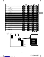
Page 32: ...觸電 因為 P C 板上有電流經過 冷凍劑回收開關 SW801 選購接頭 CN610 特殊運轉選擇開關 SW804 現有的配管開關 SW802 P C 板 疑難排解 您可以使 室外機組 P C 板上的 LED 以及室內機組有線遙控器上顯 的檢 查代碼對室外機組執 故障診斷 使 LED 和檢查代碼進 各項檢查 室內機組有線遙控器上顯 的檢查代碼 細節如室內機組的安裝 冊中所述 確認電流異常狀態 1 確認 DIP 開關 SW803 設為關 2 記下 LED800 到 LED804 的狀態 顯 模式 1 3 按 SW800 少 1 秒 LED 狀態變為顯 模式 2 4 從下表中查看顯 模式 1 與所記下 LED 狀態相同且顯 模式 2 與 LED800 到 LED804 前閃爍狀態相同的代碼 以指出原因 確認發 過的異常狀態 雖然該異常狀態不再發 1 將 DIP 開關 SW803 的位元 1 設...

Page 33: ...ROM 錯誤 10 壓縮機鎖定 11 壓縮機鎖定 12 電流偵測電路錯誤 13 壓縮機溫度調節器啟動 14 型號資料未設定 維修 P C 板上 15 MCU MCU 通訊錯誤 16 排氣溫度錯誤 17 電源異常 偵測到開相或電壓異常 18 散熱槽過熱 19 偵測到氣體洩漏 20 4 向閥反向錯誤 21 壓釋放運轉 22 室外 扇 達錯誤 23 壓縮機驅動器短路保護 24 顯 的位置偵測電路錯誤 LED 和 DIP 開 關位於室外機組 P C 板的左下 熄滅 亮起 閃爍 SW801 SW800 SW804 LED ON SW803 ON SW802 ON D800 D801 D802 D803 D804 D805 D800 D801 D802 D803 D804 D805 1 2 3 4 1 2 3 4 1 2 3 4 放 觀看 LED Toshiba 1115551210 CT CT ...

Page 34: ...管 作 3 室外機組配管斷開 或是配管洩漏氣體且配管未修理並重新填滿時 可能有 或空氣 包括濕氣 進 配管 4 無法使 冷凍劑回收裝置回收冷凍劑時 配管內可能殘留 量髒污的油或濕氣 5 市售烘乾機連接到現有的配管時 可能已產 銅綠繡 6 已回收冷凍劑後卸除現有的空調機時 確認油與普通油是否明顯不同 冷凍機油的顏 為銅繡綠 濕氣可能已與油混合 且配管內部可能已 繡 有髒污的油 量殘留物或臭味 在冷凍油中可看到 量閃亮的 屬粉塵或其他碎屑 7 空調機的壓縮機曾掉落和更換過 如果有看到髒污的油 量殘留物 閃亮的 屬粉塵或其他碎屑或混合 異物時 將發 故障 8 重複空調機的暫時安裝與卸除時 如租貸等 9 如果現有空調機的冷凍機油類型 以下油 礦物油 Suniso Freol S MS 合成油 烷基苯 HAB 冷凍機油 酯類 酯類 PVE 壓縮機的線圈絕緣可能會退化 備註 以上說明為已由本公司確認的...

Page 35: ...A 型號 3 到 5 HP 排氣管 為 15 9 mm t 將室外機組循環控制 PC 板上現有的配管開關轉 開 現有的 配管出廠時 關 t 開 請參考下表 務必設定下表中的 內容 以限制配管標準中的設備製冷循環壓 現有的配管 SW 開關 3 HP SW802 的位元 3 t 開 密封測試 乾式抽真空 冷凍劑填充 氣體洩漏檢查 試運轉 現有的配管 無法使 使 新配管 若有排放殘留物 判定有 量殘留物 清潔配管或使 新配管 由於配管壓縮須更改配管擴 螺蝐 加 尺 1 擴 螺蝐寬度 H mm 銅管外徑 6 4 9 5 12 7 15 9 19 0 適 於 R410A 17 22 26 29 36 適 於 R22 同上 24 27 同上 2 擴 加 尺 A mm 銅管外徑 6 4 9 5 12 7 15 9 19 0 適 於 R410A 9 1 13 2 16 6 19 7 24 0 適 於 R2...

Page 36: ... 䩍旾䊈 5 㮜蒦 2 ῊⰟ 㫚䶿ẅ䛿 RESET 抐 3 䩍䪩 㸃㕈ῗδ蒥3 僭 僭蒩 OPERATION 䉃Ẉ旾䊈蒦 媨Ⱅ ON Ⱅ㚽 OFF Ⱅ㚽 㚽蒩剥 扈㘫 㕈ῗẈ δ 遙控器 A B 選擇 䗱 Ⱏ 㫚Ⰴ奘 ṻ 明 䝳憫䛿 明㚽蒩 㠗㕈ῗṻ Ⱏ 㫚蒩 Ⱏ 㫚 典 㚽㐠㖱 惔㐢媅囚ạ惆壇δ 㯟ㅀ㴼Ẇ蒩 ὠ悕惉Ⲃ Ẩṻ Ⱏ 㫚 惔㐢 媨Ⱅ剮 B 媨Ⱅ 蒩 傇Ⲉ㕈ῗ ὠ 寲δ蒥梋媨媨 Ⱅ 䄵 A 媨Ⱅ δ蒦 䗱Ⱏ 㫚 惔㐢 媨Ⱅ Ẉ䝳 㚽蒩惔㐢 媅囚ⲂẈ夦㐠㖱δ 悞㐠䰜惎 杶众乕㚽蒩A 媨Ⱅ B 媨Ⱅ A 明 B 明Ệ明㚪㴍㞄 晗 䛿δ 2 䫵嬺 Ⰴ奘 㱏彾恌䛿ㅀ㴼ẆⲈ㱊 Ⱏ 㫚 Ὼ䖣惔㐢 δ 遙控器 B 設定 1 ẆⰟ 㫚ẅ䛿 RESET 蒥扈媨蒦 抐 昆䫵嬺 δ 2 Ⲃ惔㐢 Ⲉ㼑Ⱏ 㫚δ 3 䖣䯁ⲑ Ὴ惔㐢 ẅ䛿㬝㡠 CHECK 抐δ 棪䦵 ẅⲂ棪䦵ƣ00蒟蒥 a蒦δ 4 MODE...

Page 37: ...Toshiba 1115551210 COVER MEMO TSB 1115551210_EN indb 18 TSB 1115551210_EN indb 18 6 18 14 9 03 AM 6 18 14 9 03 AM ...

Page 38: ...Toshiba 1115551210 COVER MEMO TSB 1115551210_EN indb 19 TSB 1115551210_EN indb 19 6 18 14 9 03 AM 6 18 14 9 03 AM ...

Page 39: ...Toshiba 1115551210 COVER TSB 1115551210_EN indb 20 TSB 1115551210_EN indb 20 6 18 14 9 03 AM 6 18 14 9 03 AM ...

Page 40: ...Toshiba 1115551210 COVER 1115551210 TSB 1115551210_EN indb 21 TSB 1115551210_EN indb 21 6 18 14 9 03 AM 6 18 14 9 03 AM ...

Reviews: