background image

FILE NO. SVM-10049

– 

70

 –

No.

Part name

Fan motor

Procedures

1) Follow to the procedure 

till item


.

2) Loosen the set screw of the cross flow fan.
3) Remove two fixing screws of the motor 

cover

and them remove the motor cover.

4) Remove two more fixing screws of the 

motor band and remove the motor band.

Remarks

5) Pull the fan motor outward.

Set screw

Two screws on

motor band

Two screws on

motor cover

„

p

Summary of Contents for RAS-24S2AH-ES2

Page 1: ...April 2010 FILE NO SVM 10049 SERVICE MANUAL AIR CONDITIONER SPLIT WALL TYPE RAS 24SKP ES2 RAS 24SA ES2 RAS 24SKHP ES2 RAS 24S2AH ES2 ...

Page 2: ... RAS 24S2AH ES2 4 3 Indoor Unit RASP 24SKHP ES2 4 4 Outdoor Unit RAS 24S2AH ES2 5 2 RAS 24SKHP ES2 RAS 24S2AH ES2 6 1 RAS 24SKP ES RAS 24SA ES2 6 2 RAS 24SKHP ES2 RAS 24S2AH ES2 7 OPERATION DESCRIPTION 7 2 Outline of Air Conditioner Control 7 3 Description of Operation Circuit 7 4 Description of Safety and Reliability Prevention Function 7 5 One Touch Operation 7 6 Hi POWER Operation 7 7 QUIET Ope...

Page 3: ...gement 9 4 Self Diagnosis by Remote Control Check Code 9 6 9 7 Troubleshooting for Wiring Interconnect cable and Serial Signal Wire 9 8 Troubleshooting for P C Board 9 9 Troubleshooting for Remote Control 10 10 1 Indoor Unit 10 2 Outdoor Unit 11 EXPLODED VIEWS AND PARTS LIST 11 1 Indoor Unit E Parts Assy 11 2 Indoor Unit 11 3 11 4 Outdoor Unit RAS 24SA ES2 Outdoor Unit RAS 24S2AH ES2 9 5 How To Di...

Page 4: ...volume High fan m3 h Medium fan m 3 h Low fan m3 h Fan motor output W Air filter OUTDOOR UNIT Dimensions Height mm Width mm Depth mm Net weight kg Condenser type Outdoor fan type Airflow volume m3 h Fan motor output W Compressor Model Output W Safety device Louver type Usable outdoor temperature range C 4200 15 43 RAS 24SKP ES2 25 2 10 57 15 1 2070 97 0 3 9 1 0 3 8 6 1 220 240 50 Capacity Power so...

Page 5: ...h Medium fan m 3 h Low fan m3 h Fan motor output W Air filter OUTDOOR UNIT Dimensions Height mm Width mm Depth mm Net weight kg Condenser type Outdoor fan type Airflow volume m3 h Fan motor output W Compressor Model Output W Safety device Louver type Usable outdoor temperature range C 4200 15 43 10 24 RAS 24SKHP ES2 1240 1000 25 2 10 57 58 15 1 98 2050 96 240V 220V 6 82 7 28 1 220 240 50 2100 1930...

Page 6: ...perature Condition JIS C9612 Cooling Heating Indoor unit inlet air temperature DB 27 C 20 C WB 19 C 15 C Outdoor unit inlet air temperature DB 35 C 7 C WB 24 C 6 C Refrigerant 1 No need to charge 15 m or less extra refrigerant 2 Need to charge Over 15 m up to 25 m 20 g m extra refrigerant RAS 24SKHP ES2 RAS 24S2AH ES2 RAS 24SKP ES2 RAS 24SA ES2 ...

Page 7: ... 5 40 262 5 215 235 215 235 320 40 109 47 215 5 153 5 85 23 6 5 200 525 278 200 222 150 6 Hanger 8 Hanger Hanger Center line 10 Installation plate outline For stud bold For stud bold Outline of indoor unit 786 72 78 50 50 78 72 Drain hose 0 5m 12 70 Connecting pipe 0 39m Connecting pipe 0 49m 6 35 Flare Hanger Flare Hanger 132 19 157 Wireless remote controller 56 Remote controller holder 26 125 63...

Page 8: ...R6 Service port HANDLE 600 600 365 56 5 320 890 150 600 400 365 Liquid side Flare 6 35 Gas side Flare 12 70 128 82 45 Air inlet 600 or more 1000 or more Air outlet 150 or more 200 or more 320 4x 17 Long holes 365 12x17 Hole B Detail Drawing Front leg A B 56 5 25 Drain outlet 2 12x17 Hole Installation dimension Ø Ø Ø Ø Ø Ø Ø547 ...

Page 9: ...P ES2 RAS 24SA ES2 6 T3 5 L3 L N 3 1 2 RED RED RED RED BLK BLK CHASSIS GRY POWER SUPPLY 220 240 V 50 Hz SPARK KILLER MAGNETIC CONTACTOR BLK BLK RED A2 A1 52C 1 L1 2 T1 COMPRESSOR WHI PNK BLK C S R CAPACITOR CAPACITOR WHI RED FAN MOTOR BLK OUTDOOR TERMINAL BLOCK UNIT ...

Page 10: ...PNK WHI BLK WHI BLK BLK COIL FOR 4 WAY VALVE RED RED RED CAPACITOR CAPACITOR BLK BLK WHI RED CN01 CN05 GRY 1 3 5 7 9 1 3 5 7 9 BLK BLK RED RED 1 1 3 3 1 1 3 3 2 CN11 BLU YEL 1 3 1 3 1 1 3 CN02 BLU BLU 1 1 3 3 CN03 F01 250VAC T6 3A CR11 CR12 CR13 RY07 RY05 RY06 SG01 CN06 TNR R74 TNR R73 COMPRESSOR FAN MOTOR OUTDOOR TERMINAL BLOCK L N 3 1 2 S R C POWER SUPPLY 220 240V 50Hz i CHASSIS 3 2 RAS 24SKHP E...

Page 11: ...stor R01 RF 5TK1R8 No 1 8Ω P 5W ar 1 ts name 2 T Lou ype v Specifications er motor MP24Z3T Output Rated 2 W 16 poles 4 phase DC 12 V 13 G5NB 1A CA Relay RY03 Coil DC 12V 16 7mA Contact AC 250V 3A 4 2 Outdoor Unit RAS 24SA ES2 No Parts name Type Specifications Output Rated 2000W 2poles 1 phase 220 240V 50Hz 1 Compressor PA271X3CS 4MU2 Winding resistance Ω Red Black White Black at 20 C 1 27 2 10 Out...

Page 12: ... V 4 3 Indoor Unit RAS 24SKHP ES2 4 4 Outdoor Unit RAS 24S2AH ES2 No Parts name Type Specifications Output Rated 2000W 2poles 1 phase 220 240V 50Hz 1 Compressor PA271X3CS 4MU2 Winding resistance Ω Red Black White Black at 20 C 1 27 2 10 Output Rated 42W 4poles 1 phase 220 240V 50Hz 2 Fan motor for outdoor FG 240 42A 1 Winding resistance Ω Red Black White Black at 20 C 70 5 120 1 3 Running capacito...

Page 13: ... 15 Fan speed indoor 50 Hz Standard pressure P MPaG Heat exchanger Indoor unit Cross flow fan Cooling Propeller fan Outdoor unit PA271X3CS 4MUL Cooling O D 12 7 mm O D 6 35 mm Cooling Gas container connection Reinstall etc Packed valve 6 35 Packed valve 12 7 0 39 m Connecting pipe 12 7 0 49 m Connecting pipe 6 35 T P Refrigerant R410A 1 90 kg Compressor Mark means check points of Gas Leak Capillar...

Page 14: ...efrigerant R410A 2 00 kg Æ12 7 Æ6 35 Ambient temp conditions DB WB C Indoor Outdoor Standard 2 64 44 7 High 20 15 7 6 Heating Overload 1 3 54 3 80 49 3 51 0 Low 27 24 18 Low temperature 2 28 30 3 High 20 Standard 0 90 11 6 High 27 19 35 24 Cooling Overload 1 10 17 5 High 32 23 43 26 Low temperature 0 73 2 6 Low 21 15 21 15 Standard pressure P MPaG Surface temp of heat exchanger interchanging pipe ...

Page 15: ...t Restart for Compressor Motor Revolution Control Processing Timer Louver ON OFF Signal Louver Driver Operation Display Timer Display Filter Sign Display Fan Only Sign Display Indoor Fan Motor Hi Power Sign Display Louver Motor Infrared Rays Remote Control Temperature Processing Operation Operation Remote Control Operation Mode Selection AUTO COOL DRY FAN ONLY Temperature Setting Fan Speed Selecti...

Page 16: ...ommunication Louver ON OFF Signal Louver Driver Serial Signal Transmitter Receiver Serial Signal Communication Operation Display Timer Display Filter Sign Display PRE DEF Sign Display Indoor Fan Motor Hi Power Sign Display Louver Motor Infrared Rays Remote Control Temperature Processing Operation Operation Remote Control Operation Mode Selection AUTO COOL DRY HEAT FAN ONLY Temperature Setting Fan ...

Page 17: ...utton CLR 20 12 Memory and Preset button PRESET One Touch button ONE TOUCH High power button Hi POWER Economy button ECO 21 Quiet button QUIET Comfort sleep button COMFORT SLEEP Filter reset button FILTER Clock Reset button CLOCK Check button CHK 1 2 9 7 1 Remote control 7 1 1 Function of Push Putton 18 17 16 15 14 13 20 19 13 PRESET ONE TOUCH QUIET SWING TIMER ON FILTER CHK CLOCK OFF CLR SLEEP SE...

Page 18: ...han 3 seconds while the mark is blinks Press another button to turn off the mark 8 ECO indicator Indicates when the ECO is in activated Press the ECO button to start and press it again to stop operation 9 A B change indicator remote controller When the remote controller switching function is set B appears in the remote controller display When the remote controller setting is A there is no indicati...

Page 19: ...ed in the outdoor unit The air conditioner is mainly controlled by the indoor unit controller The controller operates the indoor fan motor based upon commands transmitted by the remote control and transfers the operation commands to the outdoor unit The outdoor unit receives operation commands from the indoor unit and operates the outdoor fan motor and the compressor 1 Role of indoor unit controll...

Page 20: ...et to AUTO the indoor fan motor operates as shown in Fig 7 3 3 When FAN button is set to LOW LOW MED MED or HIGH the motor operates with a constant air flow 1 2 3 3 2 5 2 1 5 1 0 5 0 5 0 M Preset temp C Room temp Preset temp 0 5 0 Preset temp ON ON OFF OFF OFF ON Compressor 4 way valve Outdoor fan OPERATION display lamp Room temp Preset temp Preset temp 24 C 2 2 5 3 C 1 5 1 0 5 0 M 1 2 3 Room temp...

Page 21: ... turning off the indoor fan motor operates in the SUPER LOW position The pattern of operation depending on the relation between room temperature and preset temperatures is shown in Fig 7 3 5 Fig 7 3 5 3 FAN button on the remote control is set to AUTO only 4 The ECO COMFORT SLEEP QUIET and Preset temp 3 2 1 0 OFF ON OFF 4 way valve Outdoor fan OPERATION Compressor ON 6min OFF 4min ON 5min OFF 5min ...

Page 22: ...No limitation while fan speed MANUAL mode is in stability A When Tsc 24 A is 24 and when Tsc 24 A is Tsc Tsc Set value Normal AUTO Line approximate H and SL with Tc Stop 46 Tc 34 45 33 33 21 32 20 A 0 A 0 A 8 A 8 Fan speed MANUAL or AUTO in starting Fan speed AUTO in stability Fan speed AUTO Fan speed MANUAL L H Up to setting speed Line approximate H and SL with Tc SL W2 Stop SL W2 Fig 7 3 8 Cold ...

Page 23: ...nd the outdoor fan motor are turned off The indoor fan motor is also turned off by the cold draft preventing control of the indoor microcomputer Then PRE DEF lamp on the indoor unit comes on The defrosting operation stops and the 4 way valve relay outdoor fan motor and the indoor fan motor are turned on automatically when the refrigerant evaporation increases to the specified temperature or when t...

Page 24: ...n the setting temperature and room temperature During the One Touch Comfort mode if the indoor unit receives any signal with other operation mode the unit will cancel the comfort mode and operates according to the signal received Operation description When an indoor unit receives One Touch Comfort Signal from the remote controller the indoor unit operates as following 1 Air conditioner starts to o...

Page 25: ... the QUIET button is pressed the fan of the indoor unit will be restricted the revolving speed at speed L until the QUIET button is pressed once again cancel Quiet mode Quiet mode is the system which control the revolving speed of indoor fan to work constantly at lower than speed L In addition noise level of indoor unit is less 1 Quiet mode is unable to work in dry mode 2 Quiet mode is appropriate...

Page 26: ...p mode has operated for 1 hour and the temperature will decrease another 1ºC after the comfort sleep mode has operated for 2 hour The value of the preset temperature on the remote control does not change The principles of comfort sleep mode are temperature reach setting temperature automatically The air condition can shut down by itself auto matically Quietness for more comfortable When room Save ...

Page 27: ...it on 7 11 Auto Restart Function This indoor unit is equipped with an automatic restarting function which allows the unit to restart operating with the set operating conditions in the event of a power supply being accidentally shut down The operation will resume without warning three minutes after power is restored This function is not set to work when shipped from the factory Therefore it is nece...

Page 28: ...me press RESET button once more or use the remote controller to turn it on 7 11 2 How to Cancel the Auto Restart Function To cancel auto restart function proceed as follows Repeat the setting procedure the unit receives the signal and beeps three times The unit will be required to be turned on with the remote controller after the main power supply is turned off When the system is on stand by not o...

Page 29: ...rmed prior to the reception of the stop code 3 After the Self Cleaning operation has been performed for the specified period the unit stops operation Unit now performing cooling or dry operation Press STOP button Only timer indicator lights and Self Cleaning operation starts Time set now elapses Operation stops During Self Cleaning operations The louver opens slightly The indoor fan operates conti...

Page 30: ...econds but it is not related to Self Cleaning function After holding about 20 seconds the air conditioner will beep 5 times and OPERATION display blinks 5 times The Self Cleaning function had been set Remark Presetting of Self Cleaning function above AUTO RESTART function had been cancelled To set AUTO RESTART again 7 12 1 Self Cleaning diagram How to cencel Self Cleaning function To cancel the Se...

Page 31: ...alls Before doing the electrical work attach an approved plug to the power supply cord Also make sure the equipment is properly earthed Appliance shall be installed in accordance with national wiring regulations If you detect any damage do not install the unit Contact your TOSHIBA dealer immediately CAUTION Exposure of unit to water or other moisture before installation could result in electric sh...

Page 32: ...ER Please make absolutely sure that the installation of this appliance is reported to the local power supplier before installation If you experience any problems or if the installation is not accepted by the supplier the service agency will take adequate countermeasures ...

Page 33: ...ke sure to run the drain hose sloped downward The auxiliary piping can be connected to the left rear left rear right right bottom right or bottom left Right Rear right Left Bottom right Rear left Bottom left Insulate the refrigerant pipes separately with insulation not together 8 mm thick heat resisting polyethylene foam 3 Batteries Cut the piping hole sloped slightly 8 Pan head wood screw Remote ...

Page 34: ...side 6 35 mm Gas side 12 70 mm Pipe insulating material polyethylene foam 8 mm thick Putty PVC tapes Fig 8 3 1 Secure the outdoor unit with fixing bolts and nuts if the unit is likely to be exposed to a strong wind Use 8 mm or 10 mm anchor bolts and nuts 150 mm 525 mm 600 mm 150 mm 45 mm 400 mm 365 mm Drain nipple mounting hole Air inlet Air outlet 33 FILE NO SVM 10049 ...

Page 35: ...e Q ty Remote control holder x 1 TOSHIBA New IAQ filter x 2 Part No 4 5 6 Part No Others Name Owner s manual Installation manual The part marked with asterisk is packaged with the outdoor unit Part name Q ty Mounting screw 4 x 25 x 6 Pan head wood screw 3 1 x 16 x 2 Drain nipple x 1 Cap water proof x 2 Screw 4 x 10 x 2 l 7 8 9 11 l TOSHIBA New IAQ filter x 2 l ...

Page 36: ...t diameter has been changed In order to increase pressure resisting strength hose materials and port size have been changed to 1 2 UNF 20 threads per inch When purchasing a charge hose be sure to confirm the port size As pressure is hight and gasification speed is fast it is difficult to read the indicated value by means of charging cylinder as air bubbles occur The size of opposite sides of flare...

Page 37: ...sturbances or noise interference The location of the remote controller should be determined as shown below 8 4 2 Drilling a Hole and Mounting Instal lation Plate Drilling a hole When install the refrigerant pipes from the rear 1 After determining the pipe hole position on the installation plate ð drill the pipe hole Ø65 mm at a slight downward slant to the outdoor side NOTE When drilling into a wa...

Page 38: ...hich discon nects all poles and has a contact separa tion of at least 3 mm must be incorporated in the fixed wiring An approved circuit breaker or switch must be used 2 Connection with power supply plug Attach power supply plug with power cord and plug it into wall outlet An approved power supply cord and plug must be used NOTE Perform wiring work being sure the wire length is long enough 8 4 4 Wi...

Page 39: ...nt panel slit Cut out the slit on the left or right side of the front panel for the left or right connection and the slit on the bottom left or side of thefront panel for the bottom left or right connection with a pair of nippers 2 Changing drain hose For left connection left bottom connection and rear left connection s piping it is necessary to relocate the drain hose and drain cap Fig 8 4 8 CAUT...

Page 40: ... the bending radius of each connection pipe Fig 8 4 15 NOTE If the pipe is incorrectly bent the indoor unit may be unstable on the wall After passing the connecting pipe through the pipe hole connect the connecting pipe to the auxiliary pipes and wrap the facing tape around them To connect the pipe after installation of the unit figure Outer diameter Slit 43 mm Use a screwdriver handle etc To the ...

Page 41: ...rm that it is firmly hooked on the installation plate For detaching the indoor unit from the installation plate pull the indoor unit toward you while pushing the bottom up at the specified places Fig 8 4 18 Push Push Fig 8 4 17 50 mm or more Do not rise the drain hose Do not form the drain hose into the waved shape Do not put the drain hose end into water Do not put the drain hose end in the drain...

Page 42: ... which provides the spaces around the outdoor unit as shown in the installation diagram A place which can bear the weight of the outdoor unit and does not allow an increase in noise level and vibration of indoor and outdoor unit 8 5 Outdoor Unit 8 5 1 Installation place Snow protection plate Snow protection hood At least 50 cm Snow accumulation line Anchor bolts Installation at least 50 cm above t...

Page 43: ...nd Liquid 7 Remove the charging hose from the service port 8 Securely tighten the caps on the packed valves Tightening torque of flare pipe connections The operating pressure of R410A is higher than that of R22 Approx 1 6 times It is therefore necessary to firmly tighten the flare pipe connecting sections which connect the indoor and outdoor units up to the specified tightening torque Incorrect co...

Page 44: ...aximum running current 15A 14A Plug socket fuse rating 20A 20A Power cord 4 mm 2 H07RN F or 60245 IEC66 or 3 5 mm2 AWG 12 5 Secure the power cord and the connecting cable with the crd clamp 6 Attach the electric parts cover and the valve cover on the outdoor unit Wire type More than 1 5 mm H07RN F or 60245 IEC66 or 1 3 mm AWG 16 2 2 NOTE Connecting cable CAUTION Wrong wiring connection may cause s...

Page 45: ...ckout procedure Knockout of Pipe Cover 44 8 5 7 Refrigerant Piping Check the flare nut connections valve stem cap connections and service dia 16mm sold on the market Also seal the screws securely with port cap connection for gas leak with a leak detection or soap water When draining completely simultaneous is needed use a drain pan Service port cap connection Flare nut connections Outdoor unit Fla...

Page 46: ... shown on the display 4 Press MODE during pushing CHK B will show on the display and 00 will disappear and the air conditioner will turn OFF The Remote Control B is memorized Note 1 Repeat above step to reset Remote Control to be A 2 Remote Control A have not A display 3 Detault setting of Remote Control from factory is A Fig 8 6 4 SLEEP PRESET ONE TOUCH FAN QUIET SWING CHK FILTER CLOCK TIMER FIX ...

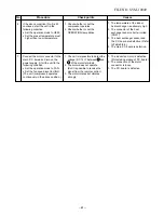
Page 47: ...r is turned on 8 The operation mode changes in the Automatic operation 9 The Fan only operation continues in the Automatic operation 10 The ECO operation or Hi POWER operation does not work 11 When Hi POWER button is pressed the display on the remote control does not change at all No Operation of air conditioner Descriptions The OPERATION lamp blinks to indicate that power is turned on If the butt...

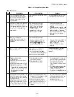
Page 48: ...Hz E OPERATION lamp is blinking 5 Hz F OPERATION and TIMER lamps are blinking 5 Hz G OPERATION TIMER and PRE DEF or FAN ONLY for cooling only model lamps are blinking Table 9 3 2 Diagnosis by detective operation The remote control does not work The outdoor fan does not rotate Turn off the power supply once then turn it on Try to operate the remote control The compressor operates The compressor doe...

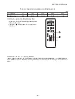
Page 49: ...oor unit will beep once Beep and the display of the remote controller will change as follows The TIMER indicator of the indoor unit flashes continuously 5 times per 1 sec Check the unit with all 52 check codes to as shown in Table 11 4 1 Press ON or OFF button to change the check code backward If there is a fault the indoor unit will beep for 10 seconds Beep Beep Beep Note the check code on the di...

Page 50: ...he indoor unit blinks when error is defected The lamp on the indoor unit blinks when error is defected The lamp on the indoor unit blinks when error is defected And it returns to the normal condition when recovering from errors The lamp on the indoor unit blinks when error is defected The lamp on the indoor unit blinks when error is detected 1 Check the indoor thermo sensor TA 2 Check the indoor P...

Page 51: ...operly Connect connector properly Indoor P C board is defective Replace P C board Operation Check item Conceivable principle cause Measure Item by symptoms Does four way valve operate properly Does coil terminal have 220 240 V in heating operation Are circuit wires normal Is outdoor P C board normal Four way valve is defective Outdoor P C board is defective CN11 220 240 V Indoor P C board is defec...

Page 52: ...fective Indoor P C board is defective Is TC sensor resistance value 10 kΩ at 25 C normal Failure 09 Other cycle error 1 Heat pump model 09 Other cycle error 2 Clean filters Replace TC sensor Charge refrigerant Replacd P C board Anti freezing operation Anti freezing operation Does indoor fan operate Are filters clogged Is charged amount of refrigerant normal Is outside air low load Indoor P C board...

Page 53: ...ly Replace TA sensor Replace P C board NO NO YES YES Is CN01 TC sensor connector connected properly Is TC sensor resistance value 10 kΩ at 25 C normal Indoor P C board is defective Connect CN01 properly Replace TC sensor Replace P C board NO NO YES YES Is TE sensor connector connected properly Is TE sensor resistance value 10 kΩ at 25 C normal Indoor P C board is defective Connect connector proper...

Page 54: ...stance value 50 kΩ at 25 C normal Are wires connected to connector properly Outdoor P C board is defective Connect wires to connector properly Check and modify charged amount of refrigerant Unit operates normally Replace TD sensor Replace P C board NO NO YES YES Is TD sensor connected properly Is TD sensor resistance value 50 kΩ at 25 C normal Outdoor P C board is defective Connect connector prope...

Page 55: ... by pressing button on remote control Does transmission mark on remote control flash normally and is its signal transmitted properly Remote control is defective Refer to 9 9 Remote Control Part C01 C02 SG01 DB01 R09 R10 T01 and IC10 are defective Is fuse F01 of indoor control board blown Is voltage DC 12V or 5V indicated on rear of indoor control board normal Microconlroler defective Replace main ...

Page 56: ... 240 V between 1 and 2 on the terminal block 2 Does the indoor fan motor operate in cooling operation In heating operation the indoor fan motor does not operate for approximately 5 minutes after it is turned on to prevent a cold air from blowing in 9 6 2 Only indoor fan motor does not operate ...

Page 57: ...n 2 and 3 on terminal block Are all of compressor cords normal Is compressor motor winding normal Check winding resistor Is capacitor for compressor normal Is overload relay normal Does compressor start Does compressor stop after a while Is gas quantity normal Check gas pressure Compressor is defective NO YES YES YES Replace P C board Gas shortage Gas leak Compressor is defective Microcomputer is ...

Page 58: ... 57 Replace transformer FILE NO SVM 10049 AC 70 100V outdoor P C board CN06 of transformer Inspection procedure RAS 24SKHP ES2 ...

Page 59: ... compressor motor winding normal Check winding resistor Is gas quantity normal Check gas pressure Is capacitor for compressor normal Is overload relay normal Does compressor start Does compressor stop after a while Replace compressor Compressor is defective Compressor is defective NO Capacitor is defective NO Overload relay is defective NO Compressor is defective NO Gas shortage Gas leak FILE NO S...

Page 60: ...and 30 seconds after star V ting the unit oltage varied between AC70 100V Abnormal condition Voltage does not vary 2 1 3 1 2 Terminal block on indoor side Terminal block Tester Red White RAS 24SKHP ES2 9 7 2 Outdoor unit stops a while after starting the unit Confirmation procedure Select one of 3 cases below and follow the procedure 1 The outdoor unit stops between 10 and 20 minutes passed after s...

Page 61: ...on procedure No Procedure Check points Causes Impluse voltage was applied or the indoor fan motor short circuited 1 The terminal block or the crossover cable is connected wrongly 2 The capacitor C01 and C02 line filter L01 resistor R09 or the diode DB01 is defective 3 C27 T01 and IC01 are defective 4 IC10 C30 C11 or T01 are defective IC03 or IC04 are defectice The lamps are defective or the housin...

Page 62: ... of the indoor heat exchanger is extremely high 2 The connector of the heat exchanger sensor short circuited CN01 3 The heat exchanger sensor and the P C board are defective Refer to Table 9 8 2 4 The main P C board is defective 1 The indoor fan motor is defective Protected operation of P C board 2 The connection of the motor connector is loose 3 The P C board is defective 1 Check whether or not t...

Page 63: ... 2 and 3 of terminal block for connecting cable Check whether or not all lamps OPERATION Auto restart TIMER FILTER and Hi power are indicated for 3 seconds and they return to normal 3 seconds later 5 Press button once to start the unit Shorten the time of the restart delay timer Set the operation mode to COOL Set the fan speed level to AUTO Set the preset temperature must lower than the room tempe...

Page 64: ...rature 0 C 10 C 20 C 25 C 30 C Resistance value 33 8 20 35 12 59 10 00 7 99 kΩ 9 8 3 How to set cancel self cleaning function The self cleaning function is set from a factory To cancel this function should keep press the RESET button on Indoor unit for 20 seconds till can hear the long combination sound and repeat the same procedure when need to set PRESET ONE TOUCH QUIET SWING TIMER ON FILTER CHK...

Page 65: ...MPORARY AUTO Can any signal tone be heard in a transistor radio when transmitting within 5 cm distance from the radio P C board is failure Replace P C board Is operation possible when the transmitter is moved nearer to the infrared signal receiver of the air conditioner Battery life Replace the batteries Reset the remote control by take off batteries Dose the transmission indicator light Is there ...

Page 66: ...shed they may ignite any oil mixed with the refrigerant gas 2 Do not use welding equipment in an airtight room Carbon monoxide poisoning may result if the room is not properly ventilated 3 Do not bring welding equipment near flammable objects Flames from the equipment may cause the flammable objects to catch fire If keeping the power on is absolutely unavoidable while doing a job such as inspectin...

Page 67: ...pcs 6 Take off four hooks of panel from rear side How to assemble the front panel 1 Press three center positions and two lower center positions of the air outlet and then hang the hanging hooks 4 pcs at the top side of the front panel to the rear plate 2 Tighten four screws Incomplete hanging or incomplete pressing may cause a dewdrops or generation of a fluttering sound 2 Screws Three hooks 4 Scr...

Page 68: ... and TC sensor leads once at the bottom 4 Disengage the display unit by simply pushing at the top of the display unit 5 Remove the fixing screw that secures the conduit mount electric parts box assembly LED assembly and remove the assembly Electric art box cover s screw TC sensor Earth Screw Fan motor connector Louver motor connector Fixing screw LED assembly Fixing screw Loof the qrunding wire p ...

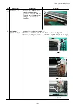
Page 69: ... and then remove other shafts while sliding the horizontal louver leftward Evaporator Heat exchanger 1 Follow to the procedure in the item 2 Remove the pipe holder from the rear side of the main unit Figure 1 3 Remove two fixing screws at the left side of the end plate of the heat exchanger Remarks Screw Screw Figure 1 Figure 2 Figure 3 Pipe hoolder ...

Page 70: ...g If the bearing is out from the housing push it into the specified position and then incorporate it in the main body Two screws Bearing Bearing base Two screws Bearing Bearing base One screw One screw 4 Remove three fixing screw at the right side of the heat exchanger and separate the heat exchanger from the back body Bearing Evaporator Heat exchanger Figure 5 Figure 4 5 Figure 4 n o ...

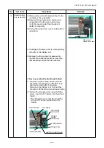
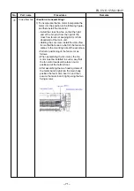
Page 71: ...oosen the set screw of the cross flow fan 3 Remove two fixing screws of the motor cover and them remove the motor cover 4 Remove two more fixing screws of the motor band and remove the motor band Remarks 5 Pull the fan motor outward Set screw Two screws on motor band Two screws on motor cover p ...

Page 72: ...e main unit Holding the set screw install the cross flow fan so that flat area on shaft of the fan motor comes to the mounting hole of the set screw q FILE NO SVM 10049 Perform positioning of the fan motor as follows When assembling the fan motor the fan motor must be installed in such a way that the fan motor leads will be taken out is positioned at the bottom front After assembling the two hooki...

Page 73: ...m the terminal Magnetic contactor 2 Remove the Panel front 2 screws 4 x 10L Pressing downward and pulling out toward you 3 Remove 2 Cord clamps 4 screws 4 x 16L and and connecting cable after removing 5 screws on the terminal block and 1 ground screw on the electrical parts base Panel Front screws Ø4 x 10L screws Ø4 x 10L 4 screws Ø4 x 16L 2 Cord clamps Running capacitor for Compressor Running cap...

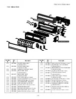
Page 74: ...02 43T60331 TERMINAL 3P 411 43T69885 ASM PCB SERV 403 43T50004 SENSOR HEAT EXCHANGER FOR 24SKP ES2 404 43T69005 SENSOR THERMOSTAT 411 43T69886 ASM PCB SERV FOR 24SKHP ES2 405 43T69736 PC BOARD ASSY WRS LED Made in Thailand 414 43T69747 ASM STEPPING MOTOR 407 43T62003 CORD CLAMP Made in Thailand 415 43T60386 MOTOR CORD Made in Thailand Description Description ...

Page 75: ...de in Thailand 204 43T80019 AIR FILTER Made in Thailand FOR 24SKHP ES2 205 43T09040 LOUVER HORIZONTAL Made in Thailand 218 43T82008 PLATE INSTALLATION Made in Thailand 206 43T70313 HOSE DRAIN Made in Thailand 219 43T49043 HOLDER PIPE Made in Thailand 207 43T79313 CAP DRAIN Made in Malaysia 220 43T62031 COVER TERMINAL Made in Thailand 208 43T21368 MOTOR FAN For 43T21344 221 43T69616 WIRELESS REMOTE...

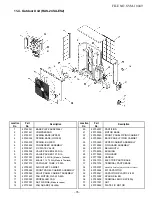
Page 76: ...SHING 9 43T46372 VALVE PACKED 12 7 DIA 28 43T19345 FIN GUARD 10 43T47331 BONNET 6 35 DIA Made in Thailand 29 43T71302 HANDLE 11 43T47333 BONNET 12 70 DIA Made in Thailand 30 43T61313 ELECTRIC PARTS BASE 12 43T47013 CAPILLARY TUBE 2 0 DIA 31 43T61314 TERMINAL PARTS BASE 13 43T00551 AIR OUTLET CABINET 32 43T52307 MAGNETIC CONTACTOR A35P For 43T52305 14 43T00548 FRONT PANEL CABINET ASSEMBLY 33 43T553...

Page 77: ...A 32 43T52307 MAGNETIC CONTACTOR A35P For 43T52305 10 43T47331 BONNET 6 35 DIA Made in Thailand 33 43T55354 MF CAPACITOR 11 43T47333 BONNET 12 70 DIA Made in Thailand 34 43T55341 CAPACITOR PLASTIC FILM 12 43T47013 CAPILLARY TUBE 2 0 DIA 36 43T60409 TERMINAL BLOCK 5P 30A 13 43T00551 AIR OUTLET CABINET 37 43T97001 NUT 14 43T00548 FRONT PANEL CABINET ASSEMBLY 38 43T00552 PLATE FIX MOTOR 15 43T00549 R...

Page 78: ... 87 FILE NO SVM 03010 1 TOSHIBA CARRIER THAILAND CO LTD 144 9 MOO 5 BANGKADI INDUSTRIAL PARK TIVANON ROAD TAMBOL BANGKADI AMPHUR MUANG PATHUMTHANI 12000 THAILAND ...

Reviews: