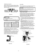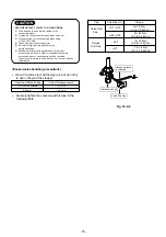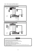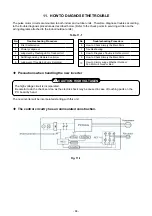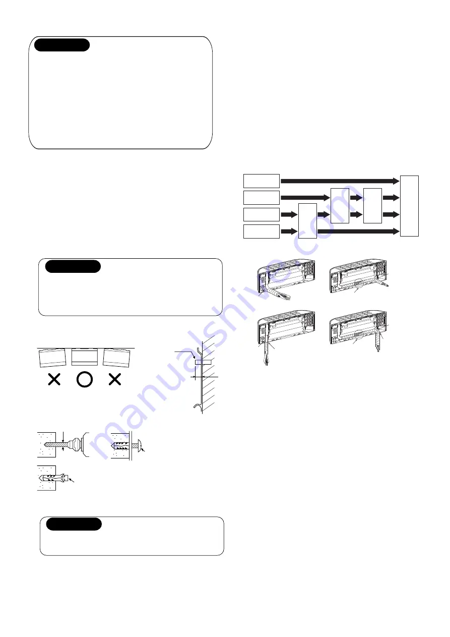
<When the installation plate is directly mounted on
the wall>
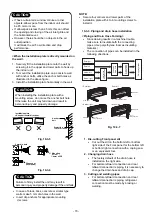
1. Securely fit the installation plate onto the wall by
screwing it in the upper and lower parts to hook up
the indoor unit.
2. To mount the installation plate on a concrete wall
with anchor bolts, utilize the anchor bolt holes as
illustrated in the above figure.
3. Install the installation plate horizontally in the wall.
CAUTION
Fig. 10-3-
5
Fig. 10-3-
6
Projection
15 mm or less
Clip anchor
(local parts)
5 mm dia. hole
Anchor
bolt
CAUTION
Failure to firmly install the unit may result in
personal injury and property damage if the unit falls.
NOTE:
•
Secure four corners and lower parts of the
installation plate with 4 to 6 mounting screws to
install it.
When installing the installation plate with a
mounting screw, do not use the anchor bolt hole.
Otherwise the unit may fall down and result in
personal injury and property damage.
Installation plate
<Keep horizontal direction>
•
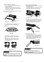
In case of block, brick, concrete or similar type
walls, make 5 mm dia. holes in the wall.
•
Insert clip anchors for appropriate mounting
screws
.
Mounting
screw
∅
4
mm
x 25
s
s
s
s
s
6
6
10-3-
3
. Piping and drain hose installation
<Piping and Drain Hose Forming>
Fig. 10-3-
7
•
Since dewing results in a machine trouble,
make sure to insulate both the connecting
pipes. (Use polyethylene foam as insulating
material.)
•
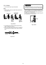
The connection of pipes can be installed in the
following directions.
1.
Die-cutting
Front panel slit
•
Cut out the slit on the bottom left or bottom
right side of the Front panel for the bottom left
or bottom right connection with a coping saw
or an equivalent tool.
2.
Changing drain hose
•
The factory default of the drain hose is
installed on the right side.
•
For bottom-leftward connection and rear
leftward connection’s piping, it is necessary to
change the drain hose and drain cap.
CAUTION
•
If have curtain rails, window cornice or other
objects, allow space from the indoor unit should
be 45 mm or more.
•
If allow space is less than 45 mm, this can affect
the opening and closing of the air inlet grille and
the horizontal louver.
•
However, there should be no objects in the air
outlet position.
It will block the air fl ow direction and drop
performance.
3. Cutting and welding pipes
•
For bottom-leftward connection and rear
leftward connection’s piping, refrigerant
connection must be made by brazing or
welding.
Rear right
Rear left
Bottom left
Bottom right
Die-cutting
Front panel slit
Changing
drain hose
Pipe cutting
and welding
Piping preparation
• Rear right
• Rear left
Cut pipe and welding
Drain hose
Drain hose
• Bottom right
• Bottom left
Drain hose
Drain hose
Cut out
Front panel slit
Cut out
Front panel slit
Cut pipe and welding
- 70 -


