background image

10-5-

3

.  

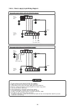
Power supply Input Wiring Diagram

1.

The power supply must be same as the rated of air conditioner.

2.

Prepare the power source for exclusive use with air conditioner.

3.

Circuit breaker must be used for the power supply line of this air conditioner.

4.

Be sure to comply power supply and connecting cable for size and wiring method.

5.

Every wire must be connected fi rmly.

6.

Perform wiring works so as to allow a general wiring capacity.

7.

Wrong wiring connection may cause some electrical part burn out.

8.

Incorrect or incomplete wiring is carried out, it will cause an ignition or smoke.

9.

This product can be connected to main power supply.

Connection to fixed wiring : A switch which disconnects all poles and has a contact separation at least 3mm must be

incorporated in the fixed wiring.

CAUTION

Power supply input at Outdoor unit Terminal Block (Recommend)

Indoor 
Terminal 
Block

Power supply input

Outdoor 
Terminal 
Block

Chassis

Chassis

Power supply input at Indoor unit Terminal Block (Optional)

Indoor 
Terminal 
Block

Power supply input

Outdoor 
Terminal 
Block

Chassis

Chassis


- 81 -

Summary of Contents for RAS-25J2AVSG-ND1

Page 1: ...SERVICE MANUAL Revised on May 2021 SPLIT TYPE Outdoor Unit RAS 25J2AVSG ND1 RAS 35J2AVSG ND1 Indoor Unit RAS 25N4KVRG ND RAS 35N4KVRG ND R32 FILE NO SVM 21017 1 ...

Page 2: ...EWS 16 5 WIRING DIAGRAM 18 6 SPECIFICATIONS OF ELECTRICAL PARTS 19 7 REFRIGERANT CYCLE DIAGRAM 20 8 CONTROL BLOCK DIAGRAM 23 9 OPERATION DESCRIPTION 25 10 INSTALLATION PROCEDURE 65 11 HOW TO DIAGNOSE THE TROUBLE 84 12 HOW TO REPLACE THE MAIN PARTS 111 13 EXPLODED VIEWS AND PARTS LIST 133 2 ...

Page 3: ...R32 only so that water and or dust does not enter Moreover do not use the existing piping because there are some problems with pressure fittings and possible impurities in existing piping CAUTION TO DISCONNECT THE APPLIANCE FROM THE MAIN POWER SUPPLY This appliance must be connected to the main power supply by a circuit breaker or a switch with a contact separation of at least 3 mm Information inc...

Page 4: ...IT MAY RESULT IN THE PIPE BURSTING AND POSSIBLE PER SONNEL INJURIES IN THE EVENT THAT THE REFRIGERANT GAS LEAKS OUT OF THE PIPE DURING THE SERVICE WORK AND THE INSTALLATION WORK IMMEDIATELY LET FRESH AIR INTO THE ROOM IF THE REFRIGERANT GAS IS HEATED SUCH AS BY FIRE GENERATION OF POISONOUS GAS MAY RESULT WARNING Never modify this unit by removing any of the safety guards or bypassing any of the sa...

Page 5: ... occur In case gas leaks and accumulates at surrounding of the unit it may cause of fire Do not install in a place that can increase the vibration of the unit Do not install in a place that can amplify the noise level of the unit or where noise and discharged air might disturb neighbors To avoid personal injury be careful when handling parts with sharp edges Please read this installation manual car...

Page 6: ...770 690 780 Outdoor unit Unit model RAS 25J2AVSG ND1 RAS 35J2AVSG ND1 Dimension Height mm 550 550 Width mm 780 780 Depth mm 290 290 Net weight kg 38 38 Compressor Motor output W 1100 1100 Type Model DX136A1T 40N Fan motor output W 43 Air flow rate Cooling Heating m3 hr 1920 1920 1980 1980 Piping Type Flare connection connection Indoor unit Liquid side mm 6 35 Gas side mm 9 52 Outdoor unit Liquid s...

Page 7: ...C WB 15oC Outdoor DB 7oC WB 6oC Indoor Air Flow High Pipe Length 5m Voltage 230V RAS 25N4KVRG ND RAS 35N4KVRG ND RAS 35N4KVRG ND RAS 25N4KVRG ND 0 20 40 60 80 100 120 15 10 5 10 Heating Capacity ratio 5 0 Outside Temperature ºC 50 55 60 65 70 75 80 85 90 95 100 105 32 33 34 35 36 37 38 39 40 41 42 43 Cooling Capacity ratio Outside Temperature oC Conditions Indoor DB 27oC WB 19oC Outdoor DB 35oC WB...

Page 8: ...ers in places where installation repairs or similar work on air conditioning equipment is performed 3 If a refrigeration gas leakage occurs during installation servicing be sure to ventilate fully If the refrigerant gas comes into contact with fire a poisonous gas may occur 4 When installing or removing an air conditioner do not allow air moisture dust or oil to remain in the refrigeration cycle O...

Page 9: ...s of socket joints Nominal diameter 1 4 3 8 1 2 5 8 Reference outer diameter of copper pipe jointed mm 6 35 9 52 12 70 15 88 Minimum joint thickness mm 0 50 0 60 0 70 0 80 3 2 2 Processing of Piping Materials When performing the refrigerant piping installation care should be taken to ensure that water or dust does not enter the pipe interior that no other oil than lubricating oils used in the inst...

Page 10: ...pe 0 to 0 5 0 to 0 5 0 to 0 5 0 to 0 5 Conventional flare tool Clutch type Wing nut type 1 0 to 1 5 1 5 to 2 0 1 0 to 1 5 1 5 to 2 0 1 0 to 1 5 2 0 to 2 5 1 0 to 1 5 2 0 to 2 5 Table 3 2 4 Dimensions related to flare processing for R22 Nominal diameter 1 4 3 8 1 2 5 8 Outer diameter mm 6 35 9 52 12 70 15 88 Thickness mm 0 8 0 8 0 8 1 0 A mm Flare tool for R22 clutch type 0 to 0 5 0 to 0 5 0 to 0 5...

Page 11: ...ning torque for R32 is the same as that for conventional R22 Incidentally when the torque is weak the gas leakage may occur When it is strong the flare nut may crack and may be made non removable When choosing the tighten ing torque comply with values designated by manufacturers Table 3 2 7 shows reference values NOTE When applying oil to the flare surface be sure to use oil designated by the manu...

Page 12: ...ifold Charge hose Vacuum pump adapter Electronic balance for refrigerant charging Leakage detector Usage Pipe flaring Flaring by conventional flare tool Connection of flare nut Evacuating refrigerant charge run check etc Vacuum evacuating Refrigerant charge Gas leakage check R32 R410A air water heat pump installation Existence of new equipment for R32 Yes Yes Yes Yes Yes Yes Yes Whether conven tio...

Page 13: ...er and the connecting port of the electronic balance and charge liquid refrigerant Indoor unit Outdoor unit Opened Opened Refrigerant cylinder with siphon Check valve Open close valve for charging Electronic balance for refrigerant charging Opened Closed Service port 3 4 Recharging of Refrigerant When it is necessary to recharge refrigerant charge the specified amount of new refrigerant according ...

Page 14: ...ler Phosphor bronze brazing filler is generally used to join copper or copper alloy 3 Low temperature brazing filler Low temperature brazing filler is generally called solder and is an alloy of tin and lead Since it is weak in adhesive strength do not use it for refrigerant pipes 1 Phosphor bronze brazing filler tends to react with sulfur and produce a fragile compound water solution which may cau...

Page 15: ... use a flux which does not contain chlorine 3 When adding water to the flux use water which does not contain chlorine e g distilled water or ion exchange water 4 Remove the flux after brazing 3 5 3 Brazing As brazing work requires sophisticated techniques experiences based upon a theoretical knowledge it must be performed by a person qualified In order to prevent the oxide film from occurring in t...

Page 16: ...195 55 16 147 21 55 147 Connecting pipe 0 61m Flare 6 35mm Connecting pipe 0 59m Installation plate hanger Installation plate hanger Installation plate hanger 286 286 590 6 5 120 156 156 144 51 74 74 300 120 144 6 5 51 225 225 199 199 Hanger Hanger Hanger Outline of indoor unit Installation plate outline 48 17 171 36 6 5 148 flare 9 52mm Center line Wireless remote controller Remote controller hol...

Page 17: ... Ø38 Drain outlet FAN GUARD COVER PV Liquid side Flare 6 35 Ø Gas side Flare 9 52 Service port Installation dimension Air outlel 100 or more 100 or more 600 or more 600 or more Air intlel Ø Ø Ø Ø6 hole 86 Ø6 hole Ø11x14 hole R15 28 A 320 R5 5 36 108 125 50 137 92 5 4 600 320 90 600 90 275 290 550 Ø 436 Z R15 50 36 2 69 Unit mm 340 17 ...

Page 18: ...RMAL YEL YELLOW BLK BLACK WHI WHITE COLOR RED RED INDICATION GRN YEL GREEN YELLOW BLU BLUE CM FM F02 T3 15A 250V F01 25A 250V Serial Communication Circuit U PMV WP 044 Outdoor Control P C Board TS TD TE TO WHI CN603 WHI CN601 WHI CN600 CN602 WHI t t t t 1 2 2 1 2 1 3 2 1 3 1 2 3 4 5 6 CN700 WHI 3 MS U U MS MS 3 WHI RED BLK RED WHI BLK ORN WHI BLK BLK Switching Power Supply RED RED P03 YEL YELLOW P...

Page 19: ...harge temp sensor TD sensor Inverter attached 62kΩ at 20 C 8 Outside air temp sensor TO sensor Inverter attached 9 Heat Exchanger temp sensor TE sensor Inverter attached 10kΩ at 25 C 10 Terminal block 6 poles JX0 6B AC 250V 30A Parts name 10kΩ at 25 C STF H01AJ1872A1 AC 220 240V No Type name Specifications 1 Fan Motor for indoor 2 Room temp sensor TA sensor 10kΩ at 25 C 3 Heat exchanger temp senso...

Page 20: ...6 35mm Thickness 0 8mm Sectional shape of heat insulator Allowable height difference 12m Allowable pipe length Strainer Pulse Modulating valve at liquid side Ø1 2 x 80 Ø1 2 x 80 TD 4 way valve Compressor DX136A1T 40N TS T2 Outdoor heat exchanger Split capillary Temp measurement Refrigerant amount 0 76kg Propeller fan OUTDOOR UNIT Muffler Muffler TE TC TA The maximum pipe length of this air conditi...

Page 21: ...nal shape of heat insulator Allowable height difference 12m Allowable pipe length Strainer Pulse Modulating valve at liquid side Ø1 2 x 80 Ø1 2 x 80 TD 4 way valve Compressor DX151A1T 30N TS T2 Outdoor heat exchanger Split capillary Temp measurement Refrigerant amount 0 76kg Propeller fan OUTDOOR UNIT Muffler Muffler TE TC TA The maximum pipe length of this air conditioner is 15 m When the pipe le...

Page 22: ... ND 1 0 to 1 1 12 to 13 43 to 44 High High 34 Tempeature condition C Heat exchanger pipe temp Connecting piping m 5 Model name Standard Indoor Outdoor Compressor pressure fan mode fan mode revolution Indoor Outdoor P MPa T1 C T2 C rps 20 7 6 RAS 25N4KVRG ND 2 1 to 2 2 34 to 35 2 to 3 High High 40 Tempeature condition C Heat exchanger pipe temp Connecting piping m Heating RAS 25N4KVRG ND 14 to 15 4...

Page 23: ...ess adapter Functions M C U Indoor Unit Control Panel Power Supply Remote Control Heat Exchanger Sensor Temperature Sensor Infrared Rays Signal Receiver Infrared Rays Initiallizing Circuit Clock Frequency Oscillator Circuit Louver Motor 36 7KHz Power Supply Circuit Noise Filter Indoor Fan Motor Timer Display Operation Display Louver Driver Louver ON OFF Signal Serial Signal Communication Serial Si...

Page 24: ...V Pulse Modulating Valve M C U Micro Control Unit I P M Intelligent Power Module For INDOOR UNIT 4 way valve P M V Inverter DC AC Inverter DC AC Outdoor Fan motor Compressor WP 044 P C B OUTDOOR UNIT Current detect Current detect M C U PWM synthesis function Input current release control IPM over current detect control Outdoor fan control High power factor correction control Inverter output freque...

Page 25: ...of operation command signal Serial signal from outdoor unit controller to indoor unit controller The following signals are sent from the outdoor unit controller The current operation mode The current compressor revolution Outdoor temperature Existence of protective circuit operation For transferring of these signals the indoor unit controller monitors the contents of signals and judges existence o...

Page 26: ...ve P M V control 39 16 Self Cleaning function 40 17 Remote A or B selection 42 9 3 Auto Restart Function 9 3 1 How to Set the Auto Restart Function 47 9 3 2 How to Cancel the Auto Restart Function 48 9 3 3 Power Failure During Timer Operation 48 9 4 Remote Controller and Its Fuctions 9 4 1 Parts Name of Remote Controller 49 9 4 2 Operation of remote control 49 18 Hi POWER Mode 42 9 4 3 Name and Fu...

Page 27: ...r POWER SEL OFF timer setup Hi POWER Fireplace Indoor unit control Command signal generating function of indoor unit operation Calculation function temperature calculation Activation compensation function of indoor fan Cold draft preventive function Timer function Indoor heat exchanger release control Indoor fan motor Louver motor Outdoor unit Outdoor unit control Frequency control of inverter out...

Page 28: ...ting the operation mode the fan speed is controlled by the previous operation mode 4 DRY operation DRY operation is performed according to the difference between room temperature and the setup temperature as shown below In DRY operation fan speed is controlled in order to prevent lowering of the room temperature and to avoid air flow from blowing directly to persons 1 Detects the room temperature ...

Page 29: ...g 1 Fig 2 2 5 Ta C 2 0 1 5 1 0 0 5 Tsc a b c d e M WC 3 4 5 L W7 Air volume AUTO L L M M H W7 L M 2 WA M H 2 WD Indication Fan speed Fan speed setup COOL ON AUTO MANUAL 3 Fan speed M L x 3 4 L 4 Fan speed M L x 2 4 L 5 Fan speed M L x 1 4 L Linear approximation from M and L Table 1 Indoor fan air flow rate Fan speed Mode RAS 25N4KVRG ND level Cooling Heating Cool Heat Dry Fan speed Fan speed rpm r...

Page 30: ...b 0 5 c 1 0 d 1 5 e 2 0 f 2 5 g 5 0 5 5 L W9 M WD 1 2 3 H WE H WE Line approximate H and SUL with Tc SUL W2 Stop 46 46 Tc 34 45 45 33 33 33 21 32 32 20 A 4 A 4 A 4 A 4 A 4 A 4 Fan speed MANUAL in starting Fan speed AUTO in stability Fan speed AUTO in starting L L M M H W8 L M 2 WA M H 2 WE Indication Fan speed Fan speed setup HEAT ON AUTO YES NO MANUAL TC 42 C Min air flow rate control Tc 52 51 42...

Page 31: ... motor stopped Air conditioner ON Remote controller YES YES NO NO Indoor unit controller Fan motor ON 3 Fan lock OFF status of fan motor continues 4 Motor operates as shown in the table below 1 Outdoor unit operation command Outdoor fan control Air conditioner OFF Alarm display Outdoor fan speed rpm In cooling operation In heating operation RAS 25J2AVSG ND1 Hz 20 4 20 4 Hz 34 2 34 2 Hz RAS 25J2AVS...

Page 32: ...e compressor speed so that electric power of the compressor drive circuit does not exceed the specified value 5 Current release control Set temp Ts Room temp Ta Correction of Hz signal Outdoor temp To Setup of current release point Capacity control continues Detection of electromotive force of compressor motor winding Detection of motor speed and rotor position Inverter output change Commutation t...

Page 33: ...he compressor speed is kept Q zone When temperature of the indoor heat exchanger drops in the range from 48 C to under 55 C the compressor speed is kept Q zone 2 When temperature of the indoor heat exchanger rises to 55 C or higher the compressor speed is reduced P zone 3 When temperature of the indoor heat exchanger does not rise to 52 C or when it drops below to 48 C the capacity control operati...

Page 34: ... considered Defrost zone In normal TO In abnormal TO A zone TO 10 C TE0 TE TO0 TO 3 C SH SH0 2 TE0 TE 3 C SH SH0 2 B zone TO 10 C TE0 TE TO0 TO 2 C SH SH0 2 TE0 TE 2 C SH SH0 2 C zone To 10 C TE 25 C SH SH0 2 D zone TO 10 C Accumulate heating operation time e minute TE 0 C E zone TO 10 C accumulate heating operation time e min No E zone If TO sensor is abnormal TO value is fixed at 10 C Returning ...

Page 35: ...e air direction of the indoor unit Description 2 Louver position in heating operation 2 Air direction adjustment The position is automatically controlled according to the operation The set louver position is stored in memory by the microcomputer The angle of the louver is indicated as the louver closes fully is 0 1 Louver position in cooling operation mode COOL HEAT and the louver returns to the s...

Page 36: ...wer Limit Position 30 o 5 o Swing range 35o SWING button during operation the louver starts swinging Upper Limit Position Lower Limit Position Fixed Position before start swing 17 5 o 17 5 o Swing range 35o 4 HADA CARE Position Air flow upward to the ceiling provide indirect air flow to body and homogenize room temperature HADA care Louver position Initial setting of Cooling storage position Louve...

Page 37: ...me Compressor speed 0Hz A zone aHz B zone a to cHz C zone cHz 0 0 5 1 0 1 5 2 0 2 5 3 0 4 0 5 0 6 0 7 0 8 0 9 0 10 0 11 0 Room temp Set temp 3 5 3 0 2 5 1 5 1 0 TSC 1 0 2 0 5 5 1H 2H 11 10 7 6 5 4 3 2 1 OFF Dry Max 12 11 9 8 10 TA 6 0 6 5 3H 4H 5 0 4 5 4 0 2 0 0 5 0 5 12 9 8 Time Zone Frequency FAN Min Hz Fan speed depend on presetting and can change every speed 1 The control target temperature in...

Page 38: ... control 1 Purpose This function detects error on the refrigerating cycle or error on the com pressor and performs protective control 2 Operation Control of the compressor speed The speed control is performed as described in the left table based upon the discharge temperature Td value 117 C 115 C 106 C 103 C 96 C Control operation Judges as an error and stops the compressor Reduce the compressor s...

Page 39: ... it is in the range of set tempera ture Discharge temp control 4 When defrost operation is performed the open degree of valve is adjusted accord ing to each setup conditions during preparation for defrost and during defrost operation 4 way valve is inversed 5 To turn off the compressor while the air conditioner stops by control of the thermostat or by remote controller adjust the open degree of va...

Page 40: ...of the operation performed prior to the reception of the stop code 3 After the Self Cleaning operation has been performed for the specified period the unit stops operating Unit now performing cooling or dry operation Press STOP button Only timer indicator lights and Self Cleaning operation starts Time set now elapses Operation stops function During Self Cleaning operations The louver opens slightl...

Page 41: ...ler to confirm setting Note Table above will show current status of Self Cleaning function Set or Cancel Self Cleaning function by push the RESET button on air conditioner When setting is changed the sound warning will alarm Beep The setting is changed following below 14 1 2 Self Cleaning function release How to set cancel Self Cleaning function To set cancel the Self Cleaning function proceed as ...

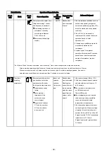
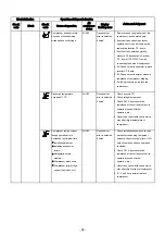
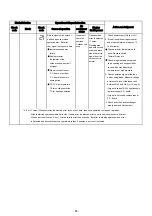
Page 42: ...nt the remote control at the indoor unit Push and hold button on back side of Remote Control 00 will be shown on the display Picture 4 B will show on MODE Press during pushing 1 the display and 00 will disappear and the air conditioner will turn OFF The Remote Control B is memorized Picture 2 Note 1 Repeat above step to reset Remote Control to be A 2 Remote Control A has not A display 3 Default se...

Page 43: ...cy rps CDU Fan Speed rpm Silent1 32 4 normal 43 8 normal Silent2 20 4 520 28 8 520 Silent1 48 6 normal 57 0 normal Silent2 28 8 600 37 8 600 Model Silent Operation Cooling RAS 25J2AVSG ND1 Heating RAS 35J2AVSG ND1 To automatically control room temperature to save energy except in DRY and FAN ONLY mode 1 Press MENU button for enter menu setting and press TEMP button to select POWER SEL 2 Enter POWE...

Page 44: ... appropriate to work with less cooling load and less heating load condition Because of the fan speed L may cause not enough the cooling capacity or heating capacity The Quiet mode selected from button The fan of the indoor unit will be restricted the revolving speed at speed UL The compressor speed is controlled as show in the figure button is The Quiet mode is canceled by pressed to select other ...

Page 45: ...ectable 2 1 Purpose Choosing the operating system as appropriate in real condition Operation Factory default setting prefer Heat pump system Through it is able to cooling only system heating only system or return to factory default Operating system setting Do cut J804 for cooling only system Do cut J805 for heating only system Do cut both of J804 and J805 for return to factory default Remote contr...

Page 46: ...it l Press button and hold 00 will show on display them press button to make 00 disappear m Press button to turn the unit ON n When short timer is activated all setting on the remote operates immediately besides all indicatiors on front panel turns ON continuously for 3 seconds FIX MODE FAN MENU FIX 4 3 FIX 25 Cord Heater Control 2 1 Purpose Base plate freeze prevention of the outdoor unit Operati...

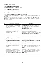
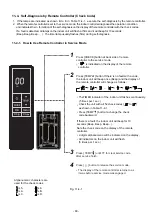
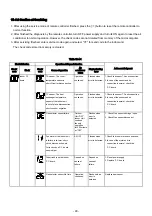
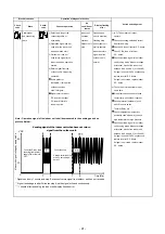
Page 47: ...n OPERATION RESET Button OPERATION RESET Button 1 The power supply to the unit must be ON The function will not set or reset if the power supply is OFF 2 Press the RESET button located on the front panel of the indoor unit for more than 3 seconds 3 After 3 seconds the unit beeps three times When the system is on stand by not operating 9 3 Auto Restart Function This indoor unit is equipped with an ...

Page 48: ...tton once more or use the remote controller to turn it on When the system is operating 9 3 3 Power Failure During Timer Operation When the unit is turned off because of power failure during timer operation the timer operation is canceled In that case set the timer operation again NOTE The Daily Timer is reset while a command signal can be received from the remote controller even if it stopped due ...

Page 49: ...0 C Fan Only No temperature indication FAN Select AUTO LOW LOW MED 3 Press MED HIGH or Quiet For dehumidification a moderate cooling performance is controlled automatically 1 Press MODE Select Dry 2 Press Set the desired temperature Min 17 C Max 30 C Note DRY mode fan speed is set to Auto only 4 DRY OPERATION MODE Select Heat 1 Press 2 Press Set the desired temperature Min 5 C Max 30 C Temperature...

Page 50: ...ing Vertical and Horizontal Swing Horizontal Left Right Swing HADA CARE FLOW 4 Confirm selected feature by press MENU button again MENU C When feature had selected will return to menu selection display triangle mark will blink 5 Leave from menu setting display by select exit and press menu button MENU C C Leave from menu setting to normal display no triangle and feature blink LOUVER SWING and HADA...

Page 51: ...ark will stop blink and setting feature will be blink instead C MENU 3 Select SILENT operation by press TEMP button C SILENT 1 SILENT 2 None 4 Confirm selected feature by press MENU button again MENU C Blink only triangle Feature already set When feature had selected will return to menu selection display triangle mark will blink 5 Leave from menu setting display by select EXIT MENU C Hi POWER OPER...

Page 52: ...lay by select EXIT MENU C Note While Fireplace operation on heating mode indoor unit fan always runs and cold air breezing might be occurred Fireplace will operate in Heating mode only TIMER OFF OPERATION To set the timer OFF when the air conditioner is operating 1 Press MENU button for enter menu setting and press TEMP button to select TIMER OFF MENU C Blink both triangle and feature mark Feature...

Page 53: ...5 seconds then remote control display will show as picture 1 for 2 seconds 1 POWER SELECTION OPERATION 6 MANUAL DEFORST OPERATION To defrosting the heat exchanger of the outdoor unit during Heating operation 7 AIR FLOW DIRECTION 1 Press FIX Move the louver in the desired vertical direction 2 Press FIX Move the louver in the desired horizontal direction 3 V V H H H DA Swing off Vertical Up Down Swi...

Page 54: ...sion 5 0 or later iOS 9 0 or later About Toshiba Home AC Control 1 Toshiba Home AC Control can control AC operation by Smartphone or tablet mobile device via internet connection 2 Everywhere control control software run on Cloud system and mobile device can set and monitor AC operation via internet connection 3 Everyone can control 1 Wireless adapter maximum 5 User use 1 email register 4 Multi AC ...

Page 55: ...nds for active AP mode 2 In case of change Wireless adapter to use with other A C need to factory reset and re process for add Wireless adapter again Build in type Press MODE button at Remote controller 5 seconds and select rb Build in type Wireless adapter already install with unit 2 Open application and select Log in 3 Enter user name and password 4 Login successful 1 Connect Wireless adapter to...

Page 56: ...MODE button 5 seconds WPS mode Manual input Wireless LED mark will blink when AP mode active 4 Active Wireless adapter by Remote controller 5 Connect with Home Wi Fi Router 6 A C add finished 7 Connect successfully Wireless LED lamp stop blink Add Wireless adapter for control by Toshiba Home AC Control application 3 AC adapter connect 56 ...

Page 57: ...ine Notification ERROR code description pop up Weekly schedule Setting Sub menu all AC Add AC Add Group Delete Group Operation Setting Sub menu group Select AC Change group name Group operation Setting Sub menu AC Operation Setting Change name Delete AC Setting temperature Actual room temp Current operation mode of each AC 57 ...

Page 58: ...ff Auto Heat Enter operation mode of All AC Enter operation mode of Group AC Enter operation mode of each AC Mode and Condition setting Mode select for Toshiba Home AC Control application Provide for 5 operation modes 58 ...

Page 59: ...hedule OFF ON Timer set OFF ON timer set 0 5 12hrs ON timer set from Off mode only Off mode Mode select Temperature set Indoor temperature Outdoor temperature Fan speed set Special feature Louver set Setting in operation mode 59 ...

Page 60: ...Maximum 3 groups 1 Group maximum 10 units Add group Please make sure Factory Reset is performed before deleting AC from mobile application See owner manual ʺPress and hold MODE button on remote control for 5 second and active dL functionʺ M MOD MODE 60 ...

Page 61: ...Weekly schedule set but not active Weekly schedule Weekly schedule set for each unit Day select Monday Sunday Weekly schedule of all AC unit Weekly schedule of all AC unit Weekly schedule set Select program for active by tick at select box Weekly schedule cancel 61 ...

Page 62: ...oring display Set cost calculate and currency Select Energy monitoring display Export data and send by Email Energy monitoring The power consumption displayed is just an estimate as it is calculated simply It may sometimes differ from the result measured by the power meter 62 ...

Page 63: ... must be installed maintained repaired and removed by a qualified installer or qualified service person Contact dealer and or service center when equipment is malfunction In case of have some problem can check from Help menu 63 ...

Page 64: ...ange indicator remote controller When the remote controller switching function is set B appears in the remote controller display When the remote controller setting is A there is no indication at this position 9 Quiet Indicates when quiet is activated Press Fan button to start and press it again to select other fan speed for operation 10 ECO indicator Indicates the selected POWER SEL level 100 75 5...

Page 65: ...tallation plate 5 Filter Mounting screw 6 For the rear left and bottom left piping Wall Cut out a piece of SPACER from indoor unit packaging box roll it and insert between the indoor unit and wall to tilt the indoor unit for better operation The auxiliary piping can be connected to rear left rear right bottom right or bottom left Bottom left Bottom right Rear left Rear right Do not allow the drain...

Page 66: ... 13 to the bottom plate of the outdoor unit before installing it 10 2 1 Optional installation parts 10 2 Installation Fixing bolt arrangement of outdoor unit Drain outlet Air inlet Air outlet 108 mm 28 mm 600 mm 320 mm 125 mm 86 mm 102 mm 90 mm Ø 3 8 m m 340 mm Part code Parts name Q ty A Refrigerant piping Liquid side Ø6 35 mm Gas side Ø9 52 mm One each B Pipe insulating material polyethylene foa...

Page 67: ...el of impurities in your operating environment Higher levels of impurities Attach filter to predetermined position of air filter Air filter Clean every 2 weeks 1 Open the air inlet grille 2 Remove the air filters 3 Vacuum or wash and then dry them 4 Reinstall the air filters and close the air inlet grille may require more frequent cleaning and replacement In all cases we recommend an additional se...

Page 68: ...ort size have been changed to 1 2 UNF 20 threads per inch When purchasing a charge hose be sure to confirm the port size As pressure is high and gasification speed is fast it is difficult to read the indicated value by means of charging cylinder as air bubbles occur The size of opposite sides of flare nuts have been increased Incidentally a common wrench is used for nominal diameters 1 4 and 3 8 B...

Page 69: ... wire lath or metal plate be sure to use a pipe hole brim ring sold separately Mounting the installation plate Fig 10 3 3 Fig 10 3 2 A place which provides the spaces around the indoor unit as shown in the diagram A place where there are no obstacles near the air inlet and outlet A place which allows easy installation of the piping to the outdoor unit A place which allows the front panel to be ope...

Page 70: ...rouble make sure to insulate both the connecting pipes Use polyethylene foam as insulating material The connection of pipes can be installed in the following directions 1 Die cutting Front panel slit Cut out the slit on the bottom left or bottom right side of the Front panel for the bottom left or bottom right connection with a coping saw or an equivalent tool 2 Changing drain hose The factory def...

Page 71: ...ut it from the main body Removed 2 screws to fix drain pan then secure remove the drain pan from the main body Drain pan Screw 2 pcs LED set Screw The drain hose can be removed by removing the screw securing the drain hose then secure rotate steel plate of drain hose to out of the Drain pan and pulling out the drain hose Screwdriver Screw Steel plate of drain hose Drain hose How to fix the drain hos...

Page 72: ... stick out of the rear plate of the indoor unit Carefully connect the auxiliary pipes and connecting pipes to each other and cut off the insulating tape wound on the connecting pipe to avoid double taping at the joint moreover seal the joint with the vinyl tape etc Since dewing results in a machine trouble make sure to insulate both the connecting pipes Use polyethylene foam as insulating material...

Page 73: ... of indoor unit may float due to the condition of piping and installer cannot fix it to the installation plate In that case use the screws provided to fix the indoor unit with the installation plate Especially when the pipes are pulled out to the left side the indoor unit must be screwed to the installation plate MOUNTING INDOOR UNIT TO THE INSTALLATION PLATE Indoor unit Wall Installation plate 8 Scr...

Page 74: ...drainage from the unit Improper drainage can result in dew dropping This air conditioner has the structure designed to drain water collected from dew which forms on the back of the indoor unit to the drain pan Therefore do not store the power cord and other parts at a height above the drain guide Fig 10 3 22 Drain hose Inside the room Shield pipe Extension drain hose Do not put the drain hose end ...

Page 75: ...ear the weight of the outdoor unit and does not allow an increase in noise level and vibration A place where the operation noise and discharged air do not disturb your neighbors A place which is not exposed to a strong wind A place free of a leakage of combustible gases A place which does not block a passage When the outdoor unit is to be installed in an elevated position be sure to secure its fee...

Page 76: ...pe cutter Fig 10 4 3 2 Insert a flare nut into the pipe and flare the pipe Projection margin in flaring A Unit mm Fig 10 4 4 90 Roughness Obliquity A Die Pipe Warp RIDGID clutch type IMPERIAL wing nut type Outer dia of copper pipe Tool used Ø6 35 1 5 to 2 0 Ø9 52 1 5 to 2 0 Ø12 70 2 0 to 2 5 Pipes thickness 0 8 mm or more Outer dia of copper pipe Tool used Conventional tool used Ø6 35 0 to 0 5 1 0...

Page 77: ...manifold valve 4 Operate the vacuum pump to start evacuating Perform evacuating for about 15 minutes if the piping length is 20 meters 15 minutes for 20 meters assuming a pump capacity of 27 liters per minute Then confirm that the compound pressure gauge reading is 101 kPa 76 cmHg 5 6 Close the low pressure side valve handle of gauge manifold Open fully the valve stem of the packed valves both sid...

Page 78: ... kgf m 14 18 N m 1 4 to 1 8 kgf m A H Hexagon wrench is required Service Port Cap Valve Rod Cap CAUTION KEEP IMPORTANT 6 POINTS FOR PIPING WORK 1 Take away dust and moisture inside of the connecting pipes 2 Tighten the connections between pipes and unit 3 Evacuate the air in the connecting pipes using a VACUUM PUMP 4 Check gas leak connected points 5 Be sure to fully open the packed valves before ...

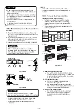
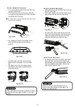
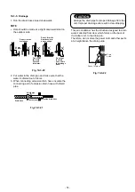
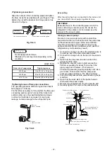
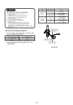
Page 79: ...e valve cover the electric parts cover and the cord clamp from the outdoor unit 2 Connect the connecting cable to the terminal as identified by the matching numbers on the terminal block of indoor and outdoor unit 3 Insert the power cord and the connecting cable carefully into the terminal block and secure it tightly with screws 4 Use vinyl tape etc to insulate the cords which are not going to be ...

Page 80: ...cable Power cord Terminal block Power cord Connecting cable connect to terminal block 1 2 3 Power supply terminal block L N 30 30 40 40 10 10 10 10 Power Supply Input at Indoor Unit Terminal Block Optional Indoor Unit Outdoor Unit Earth line Power supply cable Power supply cable connect to L N Power supply cable Terminal block L N 1 2 3 Stripping length of the power supply cable N L Earth line 50 ...

Page 81: ...7 Wrong wiring connection may cause some electrical part burn out 8 Incorrect or incomplete wiring is carried out it will cause an ignition or smoke 9 This product can be connected to main power supply Connection to fixed wiring A switch which disconnects all poles and has a contact separation at least 3mm must be incorporated in the fixed wiring CAUTION Power supply input at Outdoor unit Terminal...

Page 82: ... 2 air conditioner are installed near Remote Control B Setup 1 Press RESET button on the indoor unit to turn the air conditioner ON 2 Point the remote control at the indoor unit 3 Push and hold CHECK button on back side of Remote Control 00 will be shown on the display Picture 1 10 6 2 Remote Control A B Selection How to turn ON the Auto Restart Function Press and hold the OPERATION button on the ...

Page 83: ... process of 1 NOTE The tightness of the fabric depends on attaching the hook and loop of Velcro around the air inlet grille take appropriate action CAUTION Maintenance Shelf life Vacuum cleaner Clean when dust stuck or covers the decorative fabric Take extra care when cleaning the decorative fabric Vacuum the decorative fabric with soft brush nozzle that use for cleaning on furniture or curtain In...

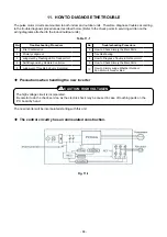
Page 84: ...eck service as the electric shock may be caused in case of touching parts on the P C board by hand The new inverter will be incorporated starting with this unit K The control circuitry has an uninsulated construction No 1 2 3 4 5 Troubleshooting Procedure First Confirmation Primary Judgment Judgment by Flashing LED of Indoor Unit Self Diagnosis by Remote Controller Judgment of Trouble by Every Sym...

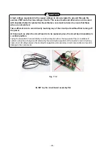
Page 85: ...t parts without first turning off the power At times such as when the circuit board is to be replaced place the circuit board assembly in a vertical position Laying the board flat on an electrically conductive object such as the top panel of the air conditioner s outdoor unit while a charge is still retained by the electrolytic capacitors of the inverter s main circuit may cause short circuiting b...

Page 86: ...e charging section before discharging an electrical shock may be caused Discharge the electrolytic capacitor completely by using soldering iron etc Discharging method 1 Remove the inverter cover plating by opening four mounting claws 2 As shown below connect the discharge resistance approx 100Ω4 0W or plug of the soldering iron to voltage between terminals of the C09 C10 WARNING ELECTRIC SHOCK is ...

Page 87: ...erated Increasing of compressor motor speed stops approx 30 seconds after operation started and then compressor motor speed increases again approx 30 seconds after In AUTO mode the operation mode is changed In HEAT mode the compressor motor speed does not increase up to the maxi mum speed or decreases before the temperature arrives at the set temperature Description The OPERATION lamp of the indoo...

Page 88: ...em B and a part of item E occur concurrently priority is given to the block of item B 3 The check codes can be confirmed on the remote controller for servicing OPERATION Flashing display 1 Hz OPERATION TIMER Flashing display 5 Hz OPERATION Flashing display 5 Hz OPERATION TIMER White Flashing display 5 Hz OPERATION Flashing display 5 Hz Protective circuit operation for indoor P C board Protective c...

Page 89: ...esthe operation condition and indicatesthe in formation of the self diagnosison the display of the remote controller with the check codes If a fault isdetected all lampson the indoor unit will flash at 5Hz and it will beep for 10seconds Beep Beep Beep The timer lamp usually flashes 5Hz during self diagnosis is indicated on the display of the remote controller Press TEMP button to change the check ...

Page 90: ...is failure lock rotor short circuit disconnection etc Or its circuit on P C board has problem Depend on Depend on Other trouble on the indoor P C board cause of cause of failure failure Action and Judgment 1 Reset power supply 2 Replace P C board Outdoor Unit OFF Indoor Unit continue fan only operation for 250 minute or OFF Flashes when error is detected Gas detector sensor failure 1 Check Gas sen...

Page 91: ...ard outdoor unit open 4 The outdoor unit abnormal stop at circuit of signal some time Signal circuit of indoor If the other check codes are found P C board or outdoor concurrently check them together P C board is failure Check protector hardware such in some period as Hi Pressure switch Thermal Relay etc Check refrigerant amount or any possibility case which may caused high temperature or high pre...

Page 92: ... OFF Flashes after Even if trying to operate again all inverter P C board error error is detected operations stop replace inverter 4 times P C board All OFF Flashes after error is detected 4 times 1 Check sensors TE TS connection In case of sensors and it s connection is normal check the inverter P C board 2 Check 4way valve operation position In case TE TS detected temperature relationship are di...

Page 93: ...es When error count comes 4 or 8 times record error to check code But after re starting operation if no error is detected and air conditioner can operate more than 6 minutes error count is cleared The others Return signal of the outdoor Indoor unit Flashes when 1 Check power supply Rate 10 including unit has been sent when operates error is detected 2 If the air conditioner repeat operates compres...

Page 94: ... All OFF Flashes after 1 Check sensors TD exceeded 117o C error is detected 2 Check refrigerant amount 4 times 3 Check P M V by measure the resistance of the coil and confirm its operation sound of initial operation etc 4 Observe any possibility cause which may affect high temperature of compressor Compressor is high current All OFF Flashes after 1 Check installation conditions such as though oper...

Page 95: ...signal of the indo unit by using diode Measure voltage at terminal block of the indoor unit between No 2 and No 3 or L2 and S If signal is varied 15 60V continuously replace inverter P C board If signal is not varied replace indoor P C board 4 Check and clean heat exchanger area Indoor and Outdoor unit Instantaneous power failure Some protector hardware of the outdoor unit open circuit of signal S...

Page 96: ...n A C by pushing button on remote controller Is voltage DC5V 12V and 15V indicated on rear of indoor control board nor mal Does transmission mark on remote controller flash normally and is its signal transmitted properly Item by symptoms Operation Check Item Considerable principle cause Measures Remote controller is defective Refer to 5 Troubleshooting for remote controller Unit operates normally ...

Page 97: ...rd is replaced Confirmation procedure YES YES NO NO Turn on power supply Does operation lamp flash Is it wired as shown in Figure below Return the wiring of the power relay is returned to the normal procedure To the paragraph of No Power turns on 97 ...

Page 98: ... motor connector CN34 Check this condition within 15 seconds after starting unit Start to operate the indoor unit in except heating operation At this time is it possible to detect DC 1V or more between 5 and 3 of motor connector CN34 Is it possible to detect DC 311 340V between 1 and 3 of motor connector CN34 Motor connection condition Is it possible to detect DC 15V between 4 and 3 of motor conne...

Page 99: ...nge airflow level to HIGH Is it possible to rotate cross flow fan by hand properly Fan motor operates normally Replace bearing of cross flow fan YES YES YES NO NO NO Does check cross flow fan bearing normal condition Replace indoor fan motor Replace main P C board Does check display on remote show high Change the new PC board Does fan speed change Replace remote Replace motor NO NO NO YES YES YES ...

Page 100: ...ove the cover of the fan motor lead wires 3 Check DC voltage with CN34 connector while the fan motor is rotating NOTE Do not disconnect the connector while the fan motor is rotating Use a thin test rod Indoor fan starts rotating when power supply is turned on Check output DC voltage of fan motor on P C board Measure voltage between 3 GND BLACK and 5 V line YELLOW of motor connector CN34 while indo...

Page 101: ...g within 5 cm distance from the radio P C board is failure Replace P C board Is operation possible when the transmitter is moved nearer to the infrared signal receiver of the air conditioner Battery life Replace the batteries Dose the transmission indicator light Is there any beep and operation Normal Remote control is failure Replace remote control Push the button YES There is no beep from the in...

Page 102: ...onds after starting of the operation Be sure to prepare a diode for judgment Normal time Voltage swings between DC15 and 60V Inverter Assembly check 11 7 1 Abnormal time Voltage does not vary 2 Outdoor unit stops in a little while after operation started Check procedure Select phenomena described below 1 The outdoor unit stops 10 to 20 minutes after operation started and 10 minutes or more are req...

Page 103: ...nd add gas if pressure is low Is connecter of coil connected to inverter Is coil of the pulse motor valve P M V correctly set Existence of condensation at outlet of P M V If there is condensation at outlet 1 4 inch Ø6 35mm valve side the valve is clogged Are temp sensors of indoor outdoor units correctly set to the holder NOTE The temperature sensors which are used to control pulse motor valve inc...

Page 104: ...ctrolytic capacitor and diode block DB01 Connect discharge resistance approx 100Ω 40W or soldering iron plug between terminals of the electro lytic capacitor 760µF of C09 C10 with printed WARNING ELECTRIC SHOCK on P C board OK if 760µF DC280 to 380V Remove CN300 while pushing the part indicated by an by an arrow because CN300 is a connector with lock Resistance between phases should be approx 33 7...

Page 105: ...k Simply the Main Parts 11 8 1 How to Check the P C Board Indoor Unit 1 Operating precautions 1 When removing the front panel or the P C board be sure to shut off the power supply breaker 2 When removing the P C board hold the edge of the P C board and do not apply force to the parts 3 When connecting or disconnecting the connectors on the P C board hold the whole housing Do not pull at the lead w...

Page 106: ...TIMER HI POWER ECO Wireless adepter are lit for 3 seconds and they return to normal 3 seconds later 1 Check whether or not the compressor operates 2 Check whether or not the OPERATION indicator flashes 1 Check whether or not the compressor operates 2 Check whether or not the OPERATION indicator flashes 1 Check it is impossible to detect the voltage AC120V or higher voltage between red and black 2 ...

Page 107: ...lue k Temperature C TA TC TO TS TE TD 1 Sensor characteristic table 11 8 2 P C Board Layout TD Discharge temp sensor TA Room temp sensor TC Heat exchanger temp sensor TO Outdoor temp sensor TS Suction temp sensor TE Outdoor heat exchanger temp sensor 15V GND 12V 5V 107 ...

Page 108: ...Valve PMV coil Model CAM MD12TCTH 5 5 Outside air temp sensor TO Discharge temp sensor TD Suction temp sensor TS Exchanger temp sensor TE 1 10Ω 33 7 1 7Ω Resistance value Position 1 31Ω Position White Red Black Measure the resistance value of each winding by using the tester Red White Black Measure the resistance value of winding by using the tester Measure the resistance value of winding by using...

Page 109: ...onverter module 1 Turn OFF the power supply breaker 2 Discharge all three capacitors completely 3 Check that the normal rectification characteristics are shown in continuity test by the tester 11 8 5 Checking Method for Each Part Case that product is good Pointer swings once and returns slowly When performing test once again under another polarity the pointer should return No Part name Checking pr...

Page 110: ...inside of the outdoor fan motor 4 Motor drive circuit failure of the outdoor P C board 3 How to simply judge whether outdoor fan motor is good or bad NOTE However GND circuit error inside of the motor may be accepted in some cases when the above check is performed When the fan motor does not become normal even if P C board is replaced replace the outdoor fan motor If the resistance value between 1...

Page 111: ...panel and cabinet Ensure that the following steps are taken when doing repairs on the refrigerating cycle 1 Do not allow any naked flames in the surrounding area If a gas stove or other appliance is being used extinguish the flames before proceeding If the flames are not extinguished they may ignite any oil mixed with the refrigerant gas 2 Do not use welding equipment in an airtight room Carbon mo...

Page 112: ...rew holding the terminal cover 3 Remove the fixing screw 2 pcs on front panel 4 Take off the hooks of front panel from top side of the back body 5 Slightly open the lower part of the front panel then pull the upper part of the front panel toward you to remove it as shown on figure Terminal cover Front panel 3 Front panel Screw 112 ...

Page 113: ...er motor from P C board assembly 4 Remove TA sensor from the cover drain Fan motor connector Vertical louver motor connector TA sensor Cover drain TA sensor TCJ sensor For Multiple model TC sensor Earth line Unit LED display Horizontal Louver motor connector Wireless adapter connector Power supply for ionizer connector P C board Connector position 4 Electric part cover Screw Pull out 113 ...

Page 114: ...rth line from the evaporator 7 Pull out TC TCJ sensor from sensor holder of the evaporator 8 Disconnect the connector of Ionizer wireless adapter and Horizontal louver motor Cover drain Take off hooks TCJ sensor For Multiple model TC sensor Earth line 4 Ionizer connector Wireless adapter Horizontal louver connector 114 ...

Page 115: ...arks Electrical part 9 Remove the fixing screw that secures unit LED display then pull out from main body 10 Remove the fixing screw that secures the electrical box then pull out from main body Screw Unit LED display Screw 4 115 ...

Page 116: ...No Part name Procedures Remarks Horizontal louver 1 Remove center shaft of the horizontal louver from the drain pan then remove side shaft Push center arm of drain pan Horizontal louver 5 116 ...

Page 117: ...cross flow fan 3 Remove 2 fixing screws of the motor band 4 Pull motor band and fan motor outward To re installation Check the type name of fan motor Keep connector position and arrange fan motor wires follow figure Hexagon screw driver Screws Fan motor Motor band Fan motor connector Fan motor wire 6 117 ...

Page 118: ... item 2 Remove fixing screw of the unit display and remove unit display 4 Remove fixing screw of drain pan 2 positions follow the figure Drain pan assembly Louver motor HR connector white Unit display 7 Screw 3 Disconnect the cord motor of Louver HR 5P 118 ...

Page 119: ...n hose Drain hose can be removed follow the procedure item After that remove the drain pan from main unit To re installation Press the drain pan into the back body Please make sure ribs of drain pan in left and right side must be install to lock position Press the right left and center arms of drain pan to back body Drain pan Rib of drain pan Rib of drain pan Left arm of drain pan Right arm of dra...

Page 120: ... the drain hose 3 When removing the drain hose be careful of any sharp edges of steel plate The edges can injuries To re installation To install the drain hose insert the drain hose firmly until the connection part contacts with heat insulator secure push steel plate of drain hose to predetermined position of Drain pan then fix it by original screw Screws Drain hose Screwdriver Insert drain hose S...

Page 121: ...1 Remove drain pan follow the procedure item and 2 Remove 2 fixing screws from the base vertical louver then remove the vertical louver assembly from the main body Vertical louver assembly Vertical louver assembly Screws Screws 9 121 ...

Page 122: ... Pull out the left hand side until the cross flow fan released from the shalf of the fan motor and thenpull out the lower side of heat exchanger follow the figure To re installation 1 To incorporate the fan motor and the motor into the position in the following figure Install the cross flow fan so that the right end if the 1st joint from the right of the cross flow fan is keep 5mm from closed wall...

Page 123: ... TC TCJ sensor and earth line from the heat exchanger 3 Remove 3 fixing screws at the left side of the heat exchanger 4 Remove 2 fixing screws at the upper and the bottom right side of the heat exchanger Screws Screws Earth line TC sensor TCJ sensor For multiple model Cover drain TA sensor Top side Right side 11 123 ...

Page 124: ...e rear side of the main unit 6 Pull out the heat exchanger to upper side To re installation Keep the back body horizontally and put the heat exchanger to the back body Make sure the heat exchanger can be assembled with the back body and secure it tightly with screws Un hook 2 position 11 124 ...

Page 125: ...urn the power supply off to stop the operation of air conditioner 2 Remove the front panel Remove the 2 fixing screws 3 Remove the electrical part base Remarks Replace terminal block microcomputer ass y and the P C board ass y Microcomputer 125 ...

Page 126: ... cabinet 1 Detachment 1 Perform step 1 in 1 2 Remove the fixing screws ST2TØ4 10L 2 pcs used to secure the front cabinet and inverter cover the screws ST2TØ4 10L 4 pcs used to secure the front cabinet at the bottom and the fixing screws ST2TØ4 10L 2 pcs used to secure the motor base The front cabinet is fitted into the side cabinet left at the front left side so pull up the top of the front cabine...

Page 127: ...ble type in some cases 4 Remove screw ST2TØ4 x 10L 4pcs fixing the terminal part of inverter box to the main body 5 Remove the front cabinet by performing step 1 in 2 and remove the fixing screws ST2TØ4 x 10L for securing the main body and inverter box 6 Remove various lead wires from the holder at upper part of the inverter box 7 Pull the inverter box upward 8 Disconnect connectors of various lea...

Page 128: ...sconnect prevention mechanism as such the lock on their housing must be released before they are disconnected 2 Remove the control board assembly from the spacer Remove the heat sink and control board assembly while keeping them screwed together 3 Remove the two fixing screws used to secure the heat sink and control board assembly 4 Mount the new control board assembly NOTE When mounting the new c...

Page 129: ...e bottom plate and heat exchanger 6 Fan motor 1 Perform work of item 1 of 1 and 2 2 Remove the flange nut fixing the fan motor a the propeller Flange nut is loosened by turning clockwise To tighten the flange nut tur counterclockwise 3 Remove the propeller fan 4 Disconnect the connector for fan motor from the inverter 5 Remove the fixing screws 3 pcs holding by hands so that the fan motor does not...

Page 130: ...e compressor from the terminal 6 Remove pipe connected to the compressor with a burner 7 Remove the fixing screw of the bottom plate and heat exchanger ST2TØ4 10L 1 pc 8 Remove the fixing screw of the bottom plate and valve fixing plate ST2TØ4 10L 1 pc 9 Pull upward the refrigeration cycle 8 Reactor 1 Perform work of item 1 of 2 and 3 2 Remove screws fixing the reactors ST2TØ4 10L 2 pcs Compressor Re...

Page 131: ...rrow mark in the right figure and remove the fa guard 2 Attachment 1 Insert claws of the fan guard in the holes of the front cabinet Push the hooking claws 9 positions by hands and fix the claws Minus screwdriver Hooking claw Check that all the hooking claws are fixed to the specified positions Electronic expansion valve coil 1 Detachment 1 Perform step 1 in all the steps in and 1 in 2 Remove the ...

Page 132: ...the heat exchanger CAUTION During the installation work and on its completion take care not to damage the coverings of the sensor leads on the edges of the metal plates or other parts It is dangerous for these coverings to be damaged since damage may cause electric shocks and or a fire CAUTION After replacing the parts check whether the positions where the sensors were installed are the proper pos...

Page 133: ...TOR BAND FRONT MOTOR COVER DRAIN COVER REFRIGERATION CYCLE ASSY HOLDER SENSOR PIPE SHIELD INSTALLATION PLATE ASSY PIPE HOLDER TERMINAL COVER ASSY WIRELESS ADAPTER WIRELESS REMOCO HOLDER REMOTE CONTROL PACKING SLEEVE PACKING CUSHION RIGHT PACKING CUSHION LEFT 219 43T20361 FRONT PANEL ASSY GRILLE OF AIR INLET ASSY AIR FILTER BACK BODY ASSY VERTICAL LOUVER ASSY DRAIN PAN ASSY HORIZONTAL LOUVER DRAIN ...

Page 134: ...43T6W727 413 43T95304 TEMPERATURE SENSOR HOUSING WiFi HOUSING LED CORD MOTOR SPACER EDGE SUPPORTER ASSY SPACER KGES 405 43T50399 TERMINAL 5P TF CORD CLAMP PC BOARD WP 501 FOR RAS 25N4KVRG ND PC BOARD WP 501 FOR RAS 35N4KVRG ND PC BOARD ASSY WRS LED TEMPERATURE SENSOR Description Description 405 412 404 TA SENSOR HOUSING WiFi 413 411 HOUSING LED CORD MOTOR 401 402 406 408 409 410 TC SENSOR 403 134 ...

Page 135: ... CABINET ASSEMBLY FRONT CABINET ASSEMBLY FIXING PLATE VALVE MOTOR BASE CONNECTION PLATE PARTITION ASSEMBLY MOTOR BASE FAN GUARD PROPELLER FAN DRAIN NIPPLE PACKED VALVE COVER ASSEMBLY HOLDER SENSOR CAP WATERPROOF CONDENSER ASSEMBLY COMPRESSOR FOR RAS 35J2AVSG ND1 COMPRESSOR FOR RAS 25J2AVSG ND1 BONNET 6 35 DIA 84 43T04416 BONNET 9 52 DIA VALVE PACKED 6 35 DIA VALVE PACKED 9 52 DIA BODY PMV COIL PMV...

Page 136: ...26 712 43T63317 TEMPERATURE SENSOR TEMPERATURE SENSOR TC SENSOR TO PC PLATE BASE HOLDER SENSOR HOLDER SENSOR HOLDER SENSOR 705 43T50353 HEATSINK PC BOARD FOR RAS 25J2AVSG ND1 PC BOARD FOR RAS 35J2AVSG ND1 TERMINAL 6P FUSE TEMPERATURE SENSOR Description Description 701 702 709 704 705 TS SENSOR 706 TD SENSOR 707 TE SENSOR 708 TO SENSOR 703 710 HOLDER SENSOR TE 711 HOLDER SENSOR TS 712 HOLDER SENSOR...

Page 137: ...144 9 MOO 5 BANGKADI INDUSTRIAL PARK TIVANON ROAD TAMBOL BANGKADI AMPHUR MUANG PATHUMTHANI 12000 THAILAND ...

Reviews: