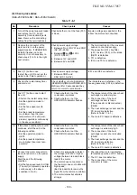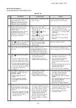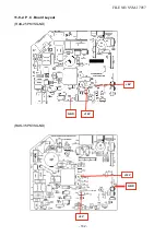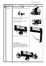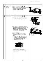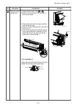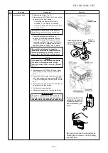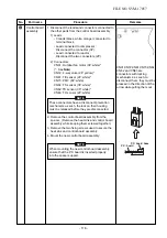
11-8-3. Indoor Unit (Other Parts)
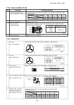
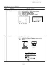
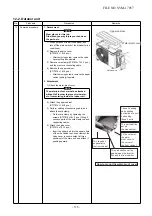
11-8-4. Outdoor Unit
No.
1
Part name
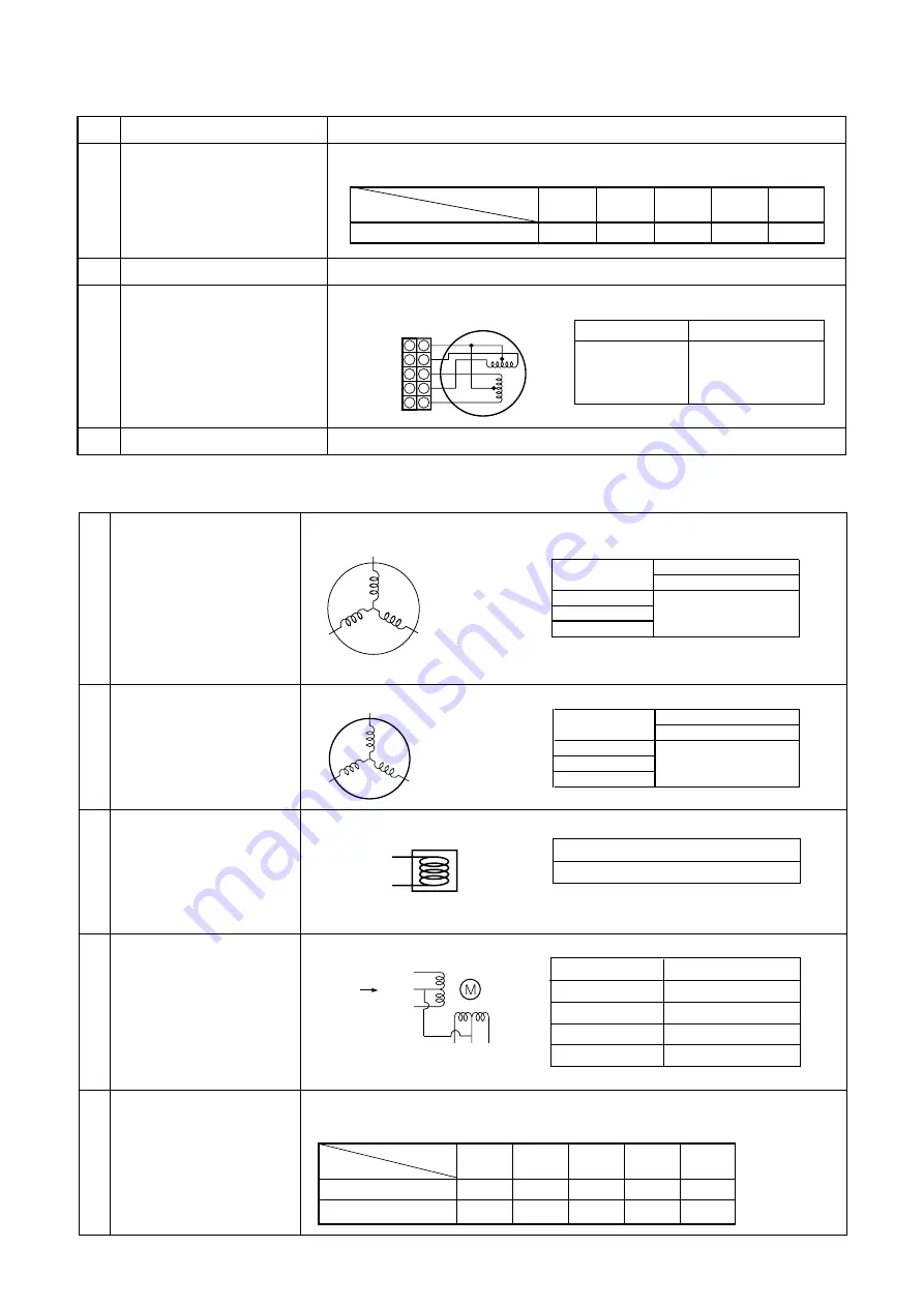
Room temp. (TA) sensor
Heat exchanger (TC) sensor
Checking procedure
Disconnect the connector and measure the resistance value with tester.
(Normal temp.)
Temperature
Sensor
TA, TC (k
Ω
)
10°C
20°C
25°C
30°C
40°C
20.7
12.6
10.0
7.9
4.5
5
4
3
2
1
White
Yellow
Yellow
Yellow
Yellow
5
4
3
2
1
Refer to 11-5-1. (5).
Measure the resistance value of each winding coil by using the tester.
(Under normal temp. 25°C)
Position
1 to 2
1 to 3
1 to 4
1 to 5
Resistance value
2
0
0
Ω
± 7%
Refer to 11-5-1. (3) and (4).
2
3
Remote controller
Louver motor
24BYJ48-
A-080
4
Indoor fan motor
1
KTN130D30UFZ
Red - White
White - Black
Black - Red
Compressor
Model : KTN130D30UFZ
2
Resistance value
WDF-340-A43-1
Red - White
White - Black
Black - Red
3
4 Pulse Modulating Valve (PMV) coil
Model : CAM-MD12TCTH-5
5 Outside air temp. sensor (TO)
Discharge temp. sensor (TD)
Suction temp. sensor (TS)
Exchanger temp. sensor (TE)
33.7 ± 1.7Ω
Resistance Valne
Position
1.02 ± 7%
Position
White
Red
Back
Measure the resistance value of each winding by using the tester.
Red
White
Black
Measure the resistance value of winding by using the tester.
at 20°C
Disconnect the connector, and measure resistance value with the tester.
(Normal temperature)
TD (k
Ω
)
Temperature
10°C
20°C
30°C
40°C
50°C
Sensor
105
64
41
27
18
TO, TS, TE (k
Ω
)
20.7
12.6
7.9
4.5
3.4
at 20°C
at 25°C
Fan motor
Model : WDF-340-A43-1
4-Way valve coil
Model : STF-H01AJ1872A1
Measure the resistance value of winding by using the tester.
Resistance value
1725 ± 172.5
Ω
at
20°C
Measure the resistance value of winding by using the tester.
Position
Gray - White
Gray - Orange
Red- Yellow
Red- Blue
Resistance value
4
2
to
50
Ω
4
2
to
50
Ω
4
2
to
50
Ω
4
2
to
50
Ω
at
20°C
1
W
COM
6
R
3
O
Y
BL
2
4
FILE NO. SVM-17057
- 104 -

