No. Part name
Procedure
Remarks
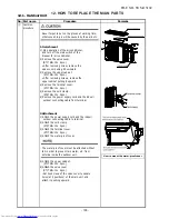
④
Side cabinet
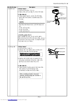
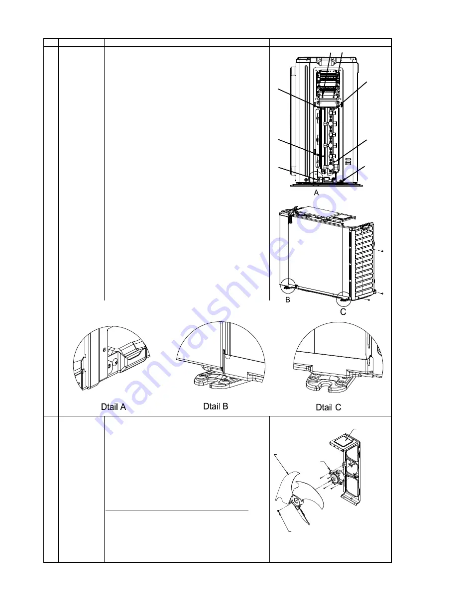
1.Side cabinet (right)
1) Perform works 1 of
①
and
②
.
2) Remove screws.
(ST1TØ4×10L 2pcs. : fix to inverter assembly)
(ST1TØ4×10L 4pcs. : fix to valve plate)
(ST1TØ4×10L 2pcs. : fix to base plate)
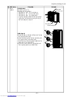
2.Side cabinet (left)
1) Perform works 1 of
①
and
②
.
2) Remove screws.
(ST1TØ4×10L
2
pc
s
. : fix to heat exchanger)
(ST1TØ4×10L
1
pc. : fix to base plate)
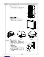
⑤
Fan
motor
1) Perform works 1 of
①
and
②
.
2) Remove the flange nut and the propeller fan.
• Flange nut is loosened by turning clockwise.
(To tighten the flange nut, turn counterclockwise.)
3) Disconnect the connector of fan motor from the
inverter.
4) Remove screws.
(ST2TØ4×20L 4pcs.)
・
Hold by hands so that the motor does not fall.
・
Precautions when assembling the propeller fan.
Tighten the flange nut using a tightening torque
of 4.9 N•m.
- 10
4
-
FILE NO. SVM-15102
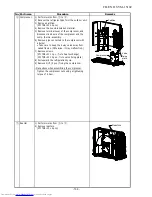
Motor base
Propeller fan
Fan motor
Flange nut
Summary of Contents for RAS-2M14S3AV-E
Page 31: ...4 1 Outdoor Unit 4 CONSTRUCTION VIEWS FILE NO SVM 15102 31 Unit mm ...
Page 116: ......

