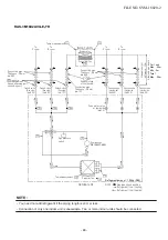
7. REFRIGERANT CYCLE DIAGRAM
7
-
1
.
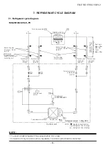
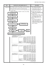
Refrigerant cycle diagram
FILE NO. SVM-18020
-2
- 46 -
P
Pr
me
es
as
s
u
u
re
re
ment
Gauge attaching port
connecting port
Packed valve
(Liquid side)
(dia.6,35)
Sectional shape
of heat insulator
Connecting pipe
Thickness : 0,8mm
dia.9,52
Packed valve
(Gas side)
(dia.9,52)
Packed valve
(Gas side)
(dia.9,52)
Connecting pipe
Thickness : 0,8mm
dia.6,35
Packed valve
(Liquid side)
(dia.6,35)
Outdoor unit
Refrigerant amount : 1,02kg (R32)
TE
TO
Propeller fan
T2
Temp.measurement
TD
Compressor
KTN130D30UFZ
High pressure
switch
TS
TGa
TGb
To
B room
To
B room
Pulse motor valve
at liquid side
(dia.1,6)
Al
lo
w
ab
le
h
ei
g
ht
difference
:
1
0
m
Al
lo
w
ab
le
p
ip
e
le
ng
th
Cross flow fan
TA
Indoor unit A
T1
Temp. measurement
TC
Evaporator
・
RAS-2M14U2AVG-E,-TR
NOTE :
Gas leak check position
Refrigerant flow (Cooling)
Refrigerant flow (Heating)
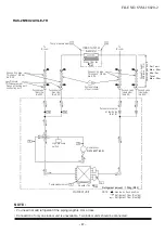
NOTE :
• You need not add refrigerant if the piping length is
30
m or less.
• Connection of only one indoor unit is unavailable. Two indoor units should be connected.
Per 1 unit
Max. : 20m
Min. : 2m
Total
Max. : 30m


