CAUTION
• Incorrect/incomplete wiring will cause
electrical
fi
res or smoke.
• Prepare the power source for exclusive
use with the air conditioner.
• This product can be connected to the main
power.
Fixed wire connections:
A switch that disconnects all poles and
has a contact separation of at least 3 mm
must be incorporated into the
fi
xed wiring.
■
Wire Connection
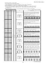
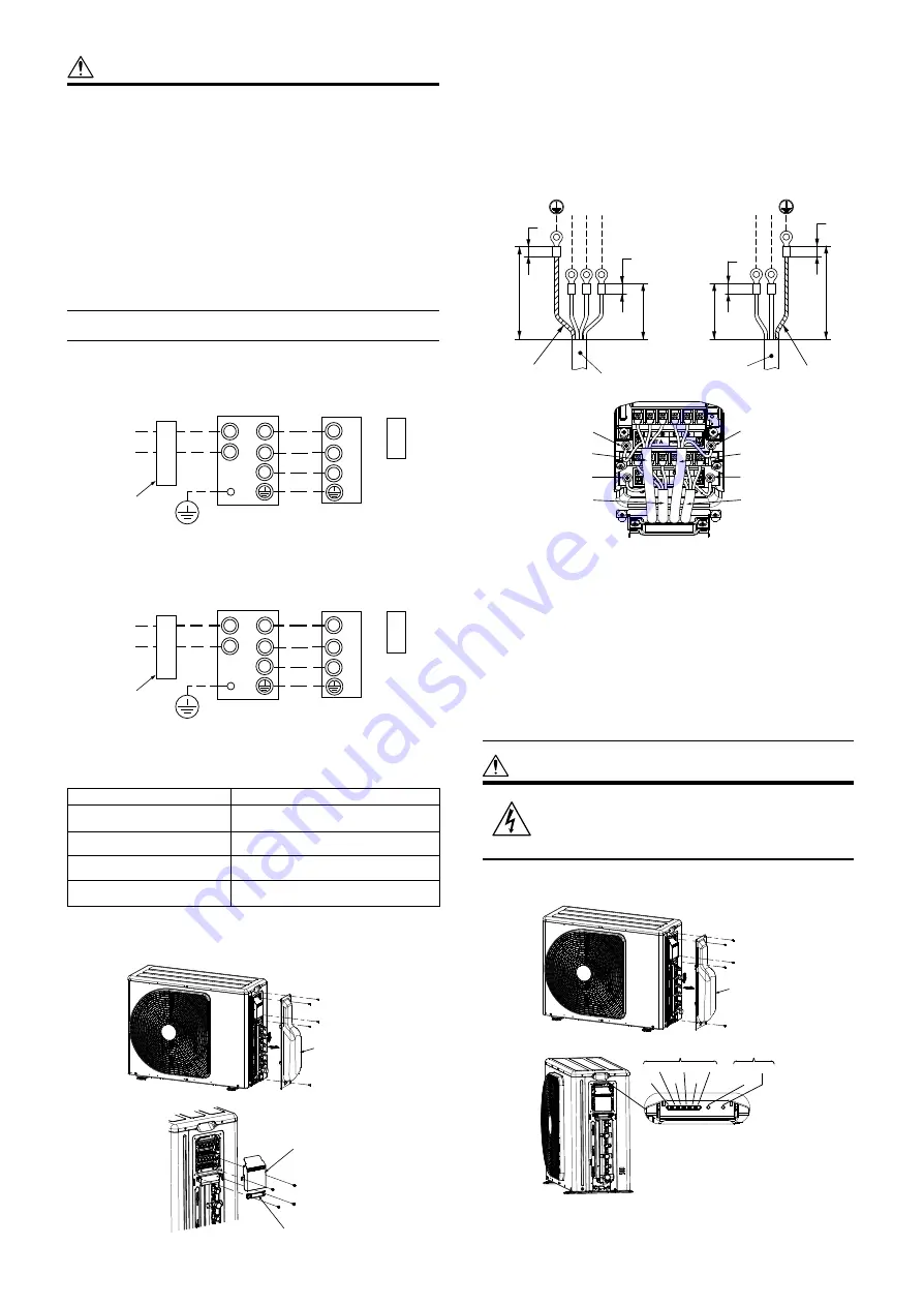
• The dash lines show on-site wiring.
(System
interconnection wires)
1(L)
2
L
N
3
1
2
3
Input power
Leakage
breaker
Indoor unit
Remote
controller
(Main circuit)
• Connect the indoor/outdoor connecting cables to the identical terminal
numbers on the terminal block of each unit.
• Incorrect connection may cause a failure.
Power supply
1ph, 50Hz, 220-240V
Maximum running current
12.6 A (for 2M14, 2M18),
13.1 A
(
for
3M
18
)
Installation fuse rating
1
5
A
(All types can be used)
Power cord
H07RN-F or 60245 IEC 66
3-core 1.5 mm
2
or more
Connecting cable
H07RN-F or 60245 IEC 66
4-core 1.0 mm
2
or more
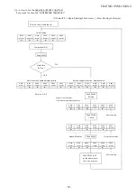
1. Remove the valve cover screws.
2. Pull the valve cover in the direction of arrow, and remove it.
3. Remove the cord clamp and the terminal cover.
Valve cover
Terminal cover
Cord clamp
4. Connect the wires for the power source and each indoor unit.
• Connect the connecting cable to the terminal as identi
fi
ed by the
matching numbers on the terminal block of the indoor and the outdoor
unit.
5. Fix the wiring connections for the power source and each indoor unit
securely using a cord clamp.
6. Attach the terminal cover and the valve cover.
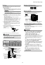
Stripping Length of connecting cable for outdoor unit
55
5
5
30
1
(L)
2
3
5
5
30
55
L N
Earth wire
Earth wire
Power cord
Connecting cable
Connecting cable
Unit B
Power cord
Connecting cable
Unit C
Connecting cable
Unit A
Earth screw
Earth screw
Earth screw
Earth screw
Grounding
This air conditioner must be grounded without fail.
• Grounding is necessary not only to safeguard against the possibility
of receiving an electric shock but also to absorb both static, which is
generated by high frequencies and held in the surface of the outdoor unit,
and noise since the air conditioner incorporates a frequency conversion
device (called an inverter) in the outdoor unit.
• If the air conditioner is not grounded, users may receive an electric shock
if they touch the surface of the outdoor unit and that unit is charged with
static.
Test run
■
Wiring/Piping Check
CAUTION
Electric current is applied on the
control board. Beware of electric
shock.
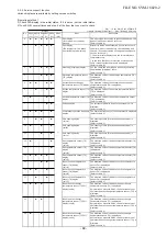
1. Remove the valve cover screws.
2. Pull the valve cover in the direction of arrow, and remove it.
Valve cover
LED
Service switches
SW01
SW02
D800
D801
D802
D803
D804
D805
(Unit : mm)
(System
interconnection wires)
2
L
N
3
L
2
3
Input power
Leakage
breaker
Indoor unit
Remote
controller
Earth
(Main circuit)
For indoor unit RAS-M series.
Earth
For indoor unit RAS-
B
series.
1(L)
FILE NO. SVM-18020
- 78 -


