background image

SERVICE MANUAL

AIR-CONDITIONER

MULTI

 TYPE

RAS-2M21U2ACVG-SG


RAS-3M31U2ACVG-SG


RAS-3M41U2ACVG-SG

December

 201

9

R32

FILE NO. SVM-19118

Summary of Contents for RAS-2M21U2ACVG-SG

Page 1: ...SERVICE MANUAL AIR CONDITIONER MULTI TYPE RAS 2M21U2ACVG SG RAS 3M31U2ACVG SG RAS 3M41U2ACVG SG December 2019 R32 FILE NO SVM 19118 ...

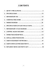
Page 2: ...VIEWS 24 5 WIRING DIAGRAM 25 6 SPECIFICATIONS OF ELECTRICAL PARTS 27 7 REFRIGERANT CYCLE DIAGRAM 28 8 CONTROL BLOCK DIAGRAM 32 9 OPERATION DESCRIPTION 34 10 INSTALLATION PROCEDURE 48 11 HOWTO DIAGNOSE THE TROUBLE 57 12 HOW TO REPLACE THE MAIN PARTS 79 13 EXPLODED VIEWS AND PARTS LIST 88 2 ...

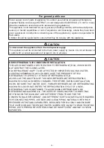
Page 3: ...cause personal injury 2 or property damage 3 1 A severe injury refers to blindness injury burns hot or cold electrical shock bone fracture or poisoning that leaves after effects and requires hospitalization or extended out patient treatment 2 Personal injury means a slight accident burn or electrical shock which does not require admission or repeated hospital treatment 3 Property damage means grea...

Page 4: ...IR CONDITIONER INSTALLATION THIS AIR CONDITIONER USES THE NEW HFC REFRIGERANT R32 WHICH DOES NOT DESTROY THE OZONE LAYER R32 REFRIGERANT IS APT TO BE AFFECTED BY IMPURITIES SUCH AS WATER OXIDIZING MEMBRANES AND OILS BECAUSE THE PRESSURE OF R32 REFRIGERANT IS APPROX 1 6 TIMES OF REFRIGERANT R22 AS WELL AS THE ADOPTION OF THIS NEW REFRIGERANT REFRIGERATING MACHINE OIL HAS ALSO BEEN CHANGED THEREFORE...

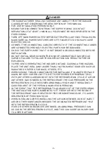
Page 5: ... A FIRE HAZARD PLACE THE UNIT WELL AWAY MORE THAN 2 M FROM HEAT SOURCES SUCH AS RADIATORS HEATERS FURNACE STOVES ETC WHEN MOVING THE AIR CONDITIONER FOR INSTALLING IT IN ANOTHER PLACE AGAIN BE VERY CAREFUL NOT TO GET THE SPECIFIED REFRIGERANT R32 WITH ANY OTHER GASEOUS BODY INTO THE REFRIGERATION CYCLE IF AIR OR ANY OTHER GAS IS MIXED IN THE REFRIGERANT THE GAS PRESSURE IN THE REFRIGERATION CYCLE ...

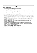
Page 6: ...t is flammable If the refrigerant leaks in the room and comes in contact with fire from a burner a heater or a cooker it may result in fire or the formation of a harmful gas Turn off any combustible heating devices ventilate the room and contact the dealer from which you purchased the unit Do not use the unit until a service person confirms that the portion from which the refrigerant leaked is rep...

Page 7: ...icated circuit and the rated voltage must be used Insufficient power supply or improper installation may cause electrical shock or fire Use a cabtyre cable to connect wires in the indoor outdoor units Midway connection stranded wire and single wire connections are not allowed Improper connection or fixing may cause a fire Wiring between the indoor unit and outdoor units must be well shaped so that...

Page 8: ...e or excess current resulting in fire or electrical shock If you detect any damage do not install the unit Contact your supplying dealer immediately Never modify this unit by removing any of the safety guards or bypassing any of the safety interlock switches Do not wash air conditioners with pressure washers Electric leaks may cause electric shocks or fires Be sure to comply with local regulations...

Page 9: ...work Failure to do so may cause personal injury when handling parts with sharp edges Do not touch the air intake section or the aluminium fins of the outdoor unit It may cause injury Do not install the outdoor unit in a place which can be a nest for small animals Small animals could enter and contact internal electrical parts causing a failure or fire Request the user to keep the place around the ...

Page 10: ...el dBA 51 53 52 Sound power level dBA 66 68 67 Compressor Model DX136A1T 40N DX151A1T 30N DX136A1T 40N Characteristic and component parts spec Type Twin rotary with DC inverter variable speed control Output W 1100 1100 1100 Fan motor Model ICF 340 A70 1 ICF 340 A70 1 ICF 340 A70 1 Type DC motor with variable speed control circuit Output W 70W 70W 70W Airflow rate m3 h 2570 2920 2920 Refrigerant Ty...

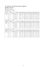
Page 11: ...0 2 10 4 20 6 10 4 97 13 13 26 2 25 2 25 2 25 4 50 5 50 375 905 1350 2 10 4 20 6 10 4 97 18 13 31 2 47 2 03 2 25 4 50 5 50 375 895 1350 2 10 4 15 6 10 5 03 18 18 36 2 25 2 25 2 25 4 50 5 50 375 885 1350 2 10 4 10 6 10 5 08 Power supply voltage Cooling capacity kW Power consumption W Operating current A Rated A B C ΣkBTU A B C Min Rated Max Min Rated Max Min Rated Max EER 2 Units 10 10 20 2 25 2 25...

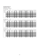
Page 12: ...Power supply voltage Cooling capacity kW Power consumption W Operating current A Rated B A C ΣkBTU A B C Min Rated Max Min Rated Max Min Rated Max EER 3 Units 10 10 10 30 2 00 2 00 2 00 2 5 6 0 7 0 415 1235 1775 2 45 6 00 8 50 4 86 13 10 10 33 2 44 1 78 1 78 2 5 6 0 7 0 400 1225 1770 2 35 5 95 8 50 4 90 18 10 10 38 2 73 1 64 1 64 2 5 6 0 7 0 400 1215 1770 2 35 5 90 8 50 4 94 13 13 10 36 2 20 2 20 ...

Page 13: ... 2 15 4 30 7 50 356 752 1790 2 04 3 53 8 10 5 72 13 13 10 36 1 55 1 55 1 20 2 15 4 30 7 50 356 752 1795 2 04 3 53 8 13 5 72 18 13 10 41 1 77 1 43 1 10 2 15 4 30 7 50 356 752 1790 2 04 3 53 8 10 5 72 13 13 13 39 1 44 1 43 1 43 2 15 4 30 7 50 356 752 1790 2 04 3 53 8 10 5 72 Power supply voltage Cooling capacity kW Power consumption W Operating current A EER A B C ΣkBTU A B C Min Rated Max Min Rated...

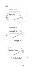
Page 14: ...A Condition Indoor side Db27oC Wb19oC Indoor unit operating 3 units Indoor unit airflow High Length of connecting pipe 5m x 3 Compressor revolution speed rps 220V 230V 240V RAS 3M31U2ACVG SG 0 0 3 0 6 0 9 0 12 0 15 0 0 10 20 30 40 50 60 70 80 90 100 Current A Condition Indoor side Db27oC Wb19oC Indoor unit operating 3 units Indoor unit airflow High Length of connecting pipe 5m x 3 Compressor revol...

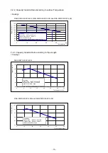
Page 15: ... Variation Ratio according to Pipe Length Cooling RAS 3M31U2ACVG SG and RAS 3M41U2ACVG SG RAS 2M21U2ACVG SG 80 85 90 95 100 105 0 5 10 15 20 25 30 35 Capacity ratio Total pipe lenght 30m Condition Indoor side Db27oC Wb19oC Outdoor side Db35oC Wb24oC Indoor unit airflow High 80 85 90 95 100 105 0 10 20 30 40 50 60 Total pipe lenght 50m Condition Indoor side Db27oC Wb19oC Outdoor side Db35oC Wb24oC ...

Page 16: ...rs in places where installation repairs or similar work on air conditioning equipment is performed 3 If a refrigeration gas leakage occurs during installation servicing be sure to ventilate fully If the refrigerant gas comes into contact with fire a poisonous gas may occur 4 When installing or removing an air conditioner do not allow air moisture dust or oil to remain in the refrigeration cycle Ot...

Page 17: ... of socket joints Nominal diameter 1 4 3 8 1 2 5 8 Reference outer diameter of copper pipe jointed mm 6 35 9 52 12 70 15 88 Minimum joint thickness mm 0 50 0 60 0 70 0 80 3 2 2 Processing of Piping Materials When performing the refrigerant piping installation care should be taken to ensure that water or dust does not enter the pipe interior that no other oil than lubricating oils used in the insta...

Page 18: ...pe 0 to 0 5 0 to 0 5 0 to 0 5 0 to 0 5 Conventional flare tool Clutch type Wing nut type 1 0 to 1 5 1 5 to 2 0 1 0 to 1 5 1 5 to 2 0 1 0 to 1 5 2 0 to 2 5 1 0 to 1 5 2 0 to 2 5 Table 3 2 4 Dimensions related to flare processing for R22 Nominal diameter 1 4 3 8 1 2 5 8 Outer diameter mm 6 35 9 52 12 70 15 88 Thickness mm 0 8 0 8 0 8 1 0 A mm Flare tool for R22 clutch type 0 to 0 5 0 to 0 5 0 to 0 5...

Page 19: ...ning torque for R32 is the same as that for conventional R22 Incidentally when the torque is weak the gas leakage may occur When it is strong the flare nut may crack and may be made non removable When choosing the tighten ing torque comply with values designated by manufacturers Table 3 2 7 shows reference values NOTE When applying oil to the flare surface be sure to use oil designated by the manu...

Page 20: ...ifold Charge hose Vacuum pump adapter Electronic balance for refrigerant charging Leakage detector Usage Pipe flaring Flaring by conventional flare tool Connection of flare nut Evacuating refrigerant charge run check etc Vacuum evacuating Refrigerant charge Gas leakage check R32 R410A air water heat pump installation Existence of new equipment for R32 Yes Yes Yes Yes Yes Yes Yes Whether conven tio...

Page 21: ...er and the connecting port of the electronic balance and charge liquid refrigerant Indoor unit Outdoor unit Opened Opened Refrigerant cylinder with siphon Check valve Open close valve for charging Electronic balance for refrigerant charging Opened Closed Service port 3 4 Recharging of Refrigerant When it is necessary to recharge refrigerant charge the specified amount of new refrigerant according ...

Page 22: ...ler Phosphor bronze brazing filler is generally used to join copper or copper alloy 3 Low temperature brazing filler Low temperature brazing filler is generally called solder and is an alloy of tin and lead Since it is weak in adhesive strength do not use it for refrigerant pipes 1 Phosphor bronze brazing filler tends to react with sulfur and produce a fragile compound water solution which may cau...

Page 23: ... use a flux which does not contain chlorine 3 When adding water to the flux use water which does not contain chlorine e g distilled water or ion exchange water 4 Remove the flux after brazing 3 5 3 Brazing As brazing work requires sophisticated techniques experiences based upon a theoretical knowledge it must be performed by a person qualified In order to prevent the oxide film from occurring in t...

Page 24: ...Outdoor Unit 4 CONSTRUCTION VIEWS Unit mm RAS 3M31U2ACVG SG RAS 3M41U2ACVG SG RAS 2M21U2ACVG SG 24 ...

Page 25: ...5 WIRING DIAGRAM Outdoor Unit RAS 2M21U2ACVG SG t t t t t t 25 ...

Page 26: ...802 D800 CONTROL BLK 3 YEL MCC 1645 GRN For D800 refer to the installation and service manual 3 YEL P C BOARD D801 MCC 1665 1 YEL 1 WHI D800 YEL 3 BLK F03 F01 CN01 T3 15A CN704 L F T3 15A RED CN300 250V CN702 CN701 CN700 250V WHI WHI F01 GRN RED YEL WHI 2 T25A P07 1 2 3 P04 P05P06 1 1 2 3 4 6 1 2 3 4 6 1 2 3 4 6 3 CN609 250V 1 PNK P01 P02 3 BLK WHI 3 5 5 5 3 MS MS M M M POWER FAN MOTOR COMPRESSOR ...

Page 27: ...oard MCC 1645 AC250V 25A 11 Fuse AC250V 6 3A 12 Fuse MountedonP C boardMCC 1645 MCC 1665 AC250V 3 15A 13 Outdoor temp sensor TO sensor 10kΩ 25 14 15 Discharge temp sensor TD sensor 50kΩ 25 16 17 Temp sensor at A room gas side TGA sensor 10kΩ 25 18 Temp sensor at B room gas side TGB sensor 10kΩ 25 20 Temp sensor at C room gas side TGC sensor only 3M series 10kΩ 25 Compressor thermo CS 12AL ON 90 OF...

Page 28: ...dia 9 52 Packed valve Gas side dia 9 52 Connecting pipe Thickness 0 8mm dia 6 35 Packed valve Liquid side dia 6 35 Outdoor unit Refrigerant amount 1 00kg R32 TO Propeller fan T2 Temp measurement TD Compressor DX136A1T 40N High pressure switch TGa TGb To B room To B room Allowable height difference 10m Allowable pipe length Per 1 unit Max 20m Min 2m Total Max 30m Cross flow fan TA Indoor unit A T1 ...

Page 29: ...side dia 9 52 Packed valve Gas side dia 12 7 Connecting pipe Thickness 0 8mm dia 6 35 Packed valve Liquid side dia 6 35 Packed valve Liquid side dia 6 35 Outdoor unit Refrigerant amount 1 40kg R32 TO Propeller fan T2 Temp measurement TD Compressor DX151A1T 30N High pressure switch Accumulator tank TGa TGb TGc To C room To B room To C room To B room Pulse motor valve at liquid side dia 1 6 Allowabl...

Page 30: ...side dia 9 52 Packed valve Gas side dia 12 7 Connecting pipe Thickness 0 8mm dia 6 35 Packed valve Liquid side dia 6 35 Packed valve Liquid side dia 6 35 Outdoor unit Refrigerant amount 1 40kg R32 TO Propeller fan T2 Temp measurement TD Compressor DX136A1T 40N High pressure switch Accumulator tank TGa TGb TGc To C room To B room To C room To B room Pulse motor valve at liquid side dia 1 6 Allowabl...

Page 31: ...h 19 0 13 0 8 to 1 0 12 to 14 38 to 44 High 31 0 18 0 8 to 1 0 12 to 14 38 to 44 High 40 0 D E 1 3 Compressor revolution Indoor Outdoor A B C rps 3 units 10 10 10 1 1 to 1 3 16 to 18 46 to 48 High 50 5 13 10 10 to 1 3 16 to 18 46 to 48 High 50 5 18 10 10 1 1 to 1 3 16 to 18 46 to 48 High 50 5 13 13 10 1 1 to 1 3 16 to 18 46 to 48 High 50 5 18 13 10 1 1 to 1 3 16 to 18 46 to 48 High 50 5 27 19 35 I...

Page 32: ...Function select MCC 1665 Control P C B MCC 1645 MAIN P C B PWM synthesis function Input current release control IPM over current detect control Highpowerfactorcorrectioncontrol Signal Communication with Control P C B Fan motor control Compressor motor control High pressure switch Case thermo Noise filter Input current Sensor Converter AC DC Inverter DC AC Inverter DC AC High power factor correctio...

Page 33: ...0Hz Signal Communication Function select MCC 1665 Control P C B MCC 1645 MAIN P C B PWM synthesis function Input current release control IPM over current detect control Highpowerfactorcorrection control Signal Communication with Control P C B Fan motor control Compressor motor control High pressure switch Case thermo Noise filter Input current Sensor Converter AC DC Inverter DC AC Inverter DC AC H...

Page 34: ...ntrol This air conditioner is a capacity variable type air conditioner Its system can control the speed of compressor motor according to load The drive circuit for the indoor motor is mounted in the indoor unit The drive circuits for outdoor motor and compressor are mounted in the outdoor unit The entire air conditioner is mainly controlled by the indoor unit controller The indoor unit controller ...

Page 35: ...fan motor control 37 3 Capacity control 38 4 Current release control 38 5 Compressor protective control 38 6 Discharge temperature control 39 7 Pulse motor valve PMV control 39 8 High pressure switch Compressor case thermostat control 39 9 3 Service switch SW01 SW0 operation 40 35 ...

Page 36: ...peration flow and applicable data etc 1 Operation control Receiving the user s operation condition setup the operation statuses of indoor outdoor units are controlled 1 The operation conditions are selected by the remote controller as shown in the below 2 A signal is sent by ON button of the remote controller 3 The signal is received by a sensor of the indoor unit and processed by the indoor contr...

Page 37: ...cording to each operation mode by the conditions of outdoor temperature To and compressor revolution the speed of the outdoor fan shown in the table is selected Compressor revolution rps 20 33 42 43 Normal operation To 38O C 350 630 800 800 28 To 38O C 350 550 630 800 15 To 28O C 300 550 550 630 10 To 15O C 300 470 470 550 5 To 10O C 300 350 350 470 0 To 5O C 300 300 300 350 To 0 0 0 300 0 300 0 3...

Page 38: ...r not is judged 4 If the current value exceeds the specified value this function reduces the compressor speed and controls speed up to the closest one commanded from the indoor unit within the range which does not exceed the specified value 5 Compressor protective control 1 This control purposes to raise the operation frequency until 45Hz for 2 minutes in order to protect the compressor Prevention...

Page 39: ...lve once until it fits to the stopper Initialize In this time Click sound may be heard 2 Adjust the open degree of valve by super heat amount SH control 3 If the discharge temperature was excessively up adjust the open degree of valve so that it is in the range of set temperature Discharge temp control Td value 120 C 115 C 111 C 108 C 101 C Control operation Judges as an error and stops the compre...

Page 40: ... does not appear in case of flashing of D804 or D805 LED display can be returned to the initial status by pushing and holding the service switches SW01 and SW02 for 5 seconds or more simultaneously D800 D801 D802 D803 D804 D805 Yellow Yellow Yellow Yellow Yellow Green In the initial status of LED display D805 is ON as below Normal D800 D801 D802 D803 D804 D805 Yellow Yellow Yellow Yellow Yellow Gr...

Page 41: ...ttings are validated 6 When you want to continue the settings moreover repeat items from 3 to 5 7 To invalidate various settings execute items 1 to 3 push SW02 and then D805 will turn off 8 Push and hold SW02 for 5 seconds or more D804 changes to slow flashing D805 is turned off and then various settings are invalidated If an unknown point generated on the way of the operation push and hold SW01 a...

Page 42: ...heck the display is kept as below Operation is up to 10 minutes After the collection is finished promptly stop the operation of all the indoor unit There are cases that the compressor restarts The outdoor unit performs cooling operation As the indoor unit does not operate by this switch setting only carry out the operation beforehand Before switch setting you have to operate in cooling mode of all...

Page 43: ...re sensor TCJ is displayed Refer to table C Discharge temperature sensor TD display Outside temperature sensor TO display The detected value of the gas temperature sensor TG is displayed Refer to table C The detected value of the gas temperature sensor TG is displayed Refer to table C The detected value of the gas temperature sensor TG is displayed Refer to table C The detected value of the indoor...

Page 44: ...mperature sensor TGb error 2 1C Gas pipe unit C temperature sensor TGc error PMV error SH 20 PMV error SH 8 20 PMV leakage error unit A 20 PMV leakage error unit B 20 PMV leakage error unit C Miswiring mispiping check error 1 Back up operation is performed without error display of the indoor unit 2 Operated normally when the air conditioners in other rooms are driven B Error display of the latest ...

Page 45: ... unit A and C 6 0 4 6 6 9 30 34 9 120 139 Trouble in unit B and C 7 5 9 7 7 9 35 39 9 140 159 Trouble in unit A B and C 8 10 14 8 8 9 40 44 9 160 179 9 15 19 9 9 9 45 49 9 180 199 10 20 24 10 10 9 50 54 9 200 219 11 25 29 11 11 9 55 59 9 220 239 12 30 34 12 12 9 60 64 9 240 259 13 35 39 13 13 9 65 69 9 260 279 14 40 44 14 14 9 70 74 9 280 299 15 45 49 15 15 9 75 79 9 300 319 16 50 54 16 16 9 80 84...

Page 46: ...me Hold time t 5 sec Push SW02 Yes No Function item Power save setting Setting OFF No limit Factory setting Setting ON Limit Setting completion Limit Refer to 9 3 6 Push SW01 8 times D800 D801 D802 D803 D804 D805 Yellow Yellow Yellow Yellow Yellow Green D800 D801 D802 D803 D804 D805 Yellow Yellow Yellow Yellow Yellow Green D800 D801 D802 D803 D804 D805 Yellow Yellow Yellow Yellow Yellow Green Push...

Page 47: ...play starts Yes No D800 D801 D802 D803 D804 D805 Yellow Yellow Yellow Yellow Yellow Green Push SW01 8 times Initial status Push SW01 02 at the same time for 5 sec or more Turn on the circuit breaker Push SW02 1 time Push SW01 Support function item Compressor operation frequency Item selecting Information display Refer to 9 3 5 Compressor ON D800 D801 D802 D803 D804 D805 Yellow Yellow Yellow Yellow...

Page 48: ...ize have been changed to 1 2 UNF 20 threads per inch When purchasing a charge hose be sure to confirm the port size As pressure is high and gasification speed is fast it is difficult to read the indicated value by means of charging cylinder as air bubbles occur The size of opposite sides of flare nuts have been increased Incidentally a common wrench is used for nominal diameters 1 4 and 3 8 By inc...

Page 49: ...necting pipe diameter RAS 2M21U2ACVG SG RAS 3M31U2ACVG SG RAS 3M41U2ACVG SG Unit C 10 or 13 6 35 9 52 mm Unit B 10 or 13 or 18 6 35 9 52 mm 6 35 9 52 mm 3 Unit A 10 or 13 or 18 6 35 9 52 mm 6 35 12 7 mm 2 Total 36 RAS 2M21U2ACVG SG 41 RAS 3M31U2ACVG SG 41 RAS 3M41U2ACVG SG All combinations that do not exceed the Total number can be installed 2 or more indoor units must be connected to an outdoor u...

Page 50: ...he admission of wind When the outdoor unit is to be mounted high on a wall take particular care to ensure that parts do not fall and that the installer is protected When doing installation work at ground level it is usual to make wiring and pipe connections to the indoor units first and then to make connections to the outdoor units However if outdoor work is difficult you can change the procedure ...

Page 51: ...are nut as much as possible with your fingers then tighten the nut using a torque wrench Be sure to tighten the nut at the specified torque value If you use one outdoor unit for several indoor units of a different class connect the largest one first A then connect the rest in the order B to C Do not remove the flare nuts for any ports you are not going to use for connection Do not leave the flare ...

Page 52: ... flare nut of the at the gas end a little to make sure that air is taken in then tighten the nut If you find air is not taken in make sure that the charge hose is connected to the port s securely Perform extraction for about 15 or more minutes and make sure that the compound pressure gauge reading is 101 kPa 76 cmHg If the compound pressure gauge reading is not 101 kPa 76 cmHg there is a possibili...

Page 53: ...ng cable to the terminal as identified by the matching numbers on the terminal block of the indoor and the outdoor unit 5 Fix the wiring connections for the power source and each indoor unit securely using a cord clamp 6 Attach the terminal cover and the valve cover Stripping Length of connecting cable for outdoor unit The dash lines show on site wiring System interconnection wires 1 2 L N 3 1 2 3...

Page 54: ...ial status D800 D801 D802 D803 D804 D805 ON OFF Cancellation method of Power Save setting Initial status D800 D801 D802 D803 D804 D805 ON OFF Push SW01 for 5 sec or more Setting mode of various functions D800 D801 D802 D803 D804 D805 ON OFF Slow Flashing 1 time sec Push SW01 8 times Power Save setting mode Limit No limit D800 D801 D802 D803 D804 D805 ON OFF Rapid Flashing 5 times sec D805 represen...

Page 55: ...heck wiring piping when the external temperature is low Also there is a possibility to misjudge if the indoor temperature becomes too low by cooling operation In that case execute the cooling operation for per room and check if the connection is normal Grounding is necessary not only to safeguard against the possibility of receiving an electric shock but also to absorb both static which is generat...

Page 56: ...he gas end 11 The refrigerants collection operation is finished in maximum 10 minutes After the collection is finished promptly stop the operation of all the indoor unit There are cases that the compressor restarts 12 When you want to start over the operation of the SW01 and SW02 press the SW01 and SW02 at the same time for 5 sec It back to the initial condition of 3 However do not execute the ope...

Page 57: ...ot normally discharge according to error contents and the voltage may remain Therefore be sure to discharge the capacitor WARNING For discharging never use a screwdriver and others for short circuiting between and electrodes As the electrolytic capacitor is one with a large capacity it is very dangerous because a large electric spark will occur Table 11 1 Discharging method Connect the discharge r...

Page 58: ...of compressor ON In DRY and SLEEP MODE FAN air flow display does not change even though FAN air flow select button is operated Increasing of compressor motor speed stops approx 30 seconds after operation started and then compressor motor speed increases again approx 30 seconds after The set value of the remote control should be below the room temperature Description The OPERATION lamp of the indoo...

Page 59: ... NOTE The contents of items B and C and a part of item E are displayed when air conditioner operates When item B and C and item B and a part of item E occur concurrently priority is given to the block of item B The check codes can be confirmed on the remote controller for servicing Indoor indication lamp flashes Which lamp does flash Item A B C D E Check code Block display OPERATION Green Flashing...

Page 60: ...lay of the remote controller Press ON or OFF button If there is no fault with a code the indoor unit will beep once Beep and the display of the remote controller will change as follows The TIMER indicator of the indoor unit flashes continuously 5 times per 1 sec Check the unit with all 52 check codes to as shown in Table 11 4 1 Press ON or OFF button to change the check code backward If there is a...

Page 61: ...nsor The room Operation Flashes when 1 Check the sensor TA and connection temperature sensor is continues error is detected 2 In case of the sensor and its short Circuit or disconnection connection is normal check the P C board TC sensor The heat Operation Flashes when 1 Check the sensor TC and connection exchanger temperature continues error is detected 2 In case of the sensor and its sensor of t...

Page 62: ...ard outdoor unit open 4 The outdoor unit abnormal stop at circuit of signal some time Signal circuit of indoor If the other check codes are found P C board or outdoor concurrently check them together P C board is failure Check protector hardware such in some period as Hi Pressure switch Thermal Relay etc Check refrigerant amount or any possibility case which may caused high temperature or high pre...

Page 63: ...Flashes after Even if trying to operate again all inverter P C board error error is detected operations stop replace inverter 4 times P C board All OFF Flashes after error is detected 4 times 1 Check sensors TE TS connection In case of sensors and it s connection is normal check the inverter P C board 2 Check 4way valve operation position In case TE TS detected temperature relationship are differe...

Page 64: ... when including unit has been sent when operates error is detected compressor operation start But after continue Flashing stop that signal is stop some time Outdoor unit and outdoor unit Instantaneous power stop start to operate failure when the return Some protector signal from the hardware of the outdoor unit is outdoor unit open normal circuit of signal Signal circuit of indoor P C board or out...

Page 65: ...rror is detected 4 times 1 Check sensors TD 2 Check refrigerant amount 3 In case of P M V exists Check P M V by measure the resistance of the coil and confirm its operation sound of initial operation etc 4 Observe any possibility cause which may affect high temperature of compressor Compressor is high current All OFF Flashes after though operation Hz is error is detected decreased to minimum limit...

Page 66: ...ed error is count as 1 time then once operation is stop and re started After re starting operation within 6 minutes if same error is detected error count is add count become 2 times When error count comes 4 8 11 or 18 times record error to check code But after re starting operation if no error is detected and air conditioner can operate more than 6 minutes error count is cleared The others includi...

Page 67: ... block varied 2 Confirm that transmission from indoor unit to outdoor unit is correctly performed based upon the following diagram NOTE Measurement should be performed 2 minutes and 30 seconds after starting of the operation Be sure to prepare a diode for judgment Normal time Voltage swings between DC15 and 60V Inverter Assembly check Abnormal time Voltage does not vary 2 Outdoor unit stops in a l...

Page 68: ...s some errors some LEDs go on or flash according to the error as described in Error display table Refer to P 69 3 Specific operation display When SW01 or SW02 is pushed and a specific operation is operated some LEDs go on or flash D801 to D804 Yellow LED Display part on MCC 1665 Control PCB Part No Specifications Operation contents D502 D511 D517 Orange LED Indoor Outdoor communication Serial comm...

Page 69: ... Rapid Flashing 5 times sec Slow Flashing 1 time sec Display Indoor Description D800 D801 D802 D803 D804 D805 check code YL YL YL YL YL GN Normal operation no error 1C Compressor case thermostat error 21 High pressure switch error 1C Compressor system error 1d Compressor lock 1F Compressor breakdown 14 Driving element short circuit 16 Position detection circuit error 17 Current detection circuit e...

Page 70: ...ES NO YES NO NO NO NO NO Is PMV under correct conditions Is service valve fully opened Are CN609 of P C board MCC 1645 connection and case thermostat correct Check ourdoor P C B MCC 1645 Defect Replace Short each pins of CN500 Can compressor operate Repair defective position Recharge refrigerant Is there gas leak Is there refrigerant shortage Check compressor Rare short etc Defect Replace NO YES Y...

Page 71: ...ce Check wiring construction Ask repair of power supply Check outdoor P C B MCC 1645 Defect Replace Is connection of CN600 on P C B MCC 1665 correct Is resistance value of TD sensor correct Correct connector Sensor error Replace Check outdoor P C B MCC 1665 Defect Replace Is connection of CN602 on P C B MCC 1665 correct Is resistance value of TO sensor correct Check code Outdoor LED display Check ...

Page 72: ...ct short circuit Check outdoor P C B MCC 1645 and MCC 1665 Defect Replace Compressor lock Replace 1 1 Does PMV correctly operate Is there refrigerant stagnation Is compressor under correct condition Is AC mains voltage correct 198 to 264V Does something block the ventilation around the heat sink Does something air flow from the fan Apply radiation grease to objective parts Retightening of screws I...

Page 73: ...utdoor unit A room gas side temp sensor TGa error B room gas side temp sensor TGb error C room gas side temp sensor TGc error ON 3 sec ON 0 5 sec OFF z OFF z z z YES NO Communication error between MCUs Are connections of CN802 on P C B MCC 1665 and CN806 on P C B MCC 1645 correct Correct connection Check outdoor P C Boards Defect Replace z z Is AC mains voltage correct 198 to 264V Is wire connecti...

Page 74: ...overload YES YES NO NO NO NO YES YES Check code 1E Outdoor LED display Check and troubleshooting Item without special mention indicates part of outdoor unit Discharge temp error Does an abnormal overload happen Is AC mains voltage correct 198 to 264V Is wire connection correct Compressor lead Board side Compressor Side Reactor lead Power supply lead Check wiring construction Ask repair of power su...

Page 75: ... sensor TC sensor YES NO OK Error Repair defective position Replace defective part Correct connector Sensor error Replace Check outdoor P C B MCC 1665 and indoor A room P C board Defect Replace Is PMV under correct conditions Check temp sensor of A room indoor unit TA sensor TC sensor YES NO OK Error Check code Outdoor LED display Check and troubleshooting Item without special mention indicates pa...

Page 76: ...ly operate B Cooling operation B Cooling operation Doesn t high pressure switch operate Are parts of high pressure switch normal Reset the power supply and then do a trial operation according to the season Is there any element which blocks heat exchanger of the outdoor unit Clogging of heat exchanger Short circuit Parts check Defective Replace Elimination of blocking element Check IPDU PC board De...

Page 77: ...the connector and measure resistance value with the tester Normal temperature Position Red White White Black Black Red Resistance value 18 80 2Ω Temperature Sensor TD kΩ TO kΩ TGa to TGc kΩ 10 C 20 C 25 C 40 C 50 C 105 64 51 27 18 20 6 12 6 10 0 5 1 3 4 20 0 12 5 10 0 5 3 3 6 4 High pressure switch Model ACB 1UB177W Check conduction by using the tester 100 30 40 50 60 70 80 90 20 10 0 0 10 20 30 4...

Page 78: ...rror inside of the outdoor fan motor 4 Motor drive circuit error of the outdoor P C board 3 How to simply judge whether outdoor fan motor is good or bad Turn OFF the breaker Fan motor is normal Does the fan rotate without trouble when rotating it with hands Disconnect connector of the outdoor fan motor from P C board MCC 1645 Outdoor P C board error Fan motor error YES YES NO NO If the resistance ...

Page 79: ...10L 2pcs 5 Remove the cord clamp ST2TØ4 10L 2pcs 6 Remove the power supply cord and the indoor outdoor connecting cable from terminal 2 Attachment 1 Attach the power supply cord and the indoor outdoor connecting cable to terminal 2 Attach the cord clamp ST2TØ4 10L 2pcs 3 Attach the terminal cover ST1TØ4 10L 2pcs 4 Attach the water proof cover The water proof cover must be attached without fail in ...

Page 80: ...eft side so pull up the top of the front cabinet to remove it 2 Attachment 1 Insert the claw on the front left side into the side into the side cabinet left 2 Hook the bottom part of the front right side onto the concave section of the base plate Insert the claw of the side cabinet right into the square hole in the front cabinet 3 Return the screws that were removed above to their original positio...

Page 81: ...he cover under inverter box ST1TØ4 10L 1pc 4 Disconnect the leads connected to the other parts from the inverter assembly Lead connected to compressor 3P white Lead connected to reactor 2P 2 white 5 Cut the banding band 3pcs 6 Remove the black color lead wire ST2TØ4 8L 1pc 7 Remove the duct cover of inverter box ST1TØ4 10L 2pcs 8 Remove the inverter box and inverter cover 9 Remove the power supply...

Page 82: ...ontrol P C board CN01 AC IN 2P Red CN02 Serial communication 3P Black CN600 TD sensor 3P white CN602 TO sensor 2P white CN604 TGa sensor 2P yellow CN605 TGb sensor 2P red CN606 TGc sensor 2P green CN700 PMV A 6P yellow CN701 PMV B 6P red CN702 PMV C 6P green CN805 Display P C board 10P white Connected connector of main and control CN806 and CN802 5P blue 11 Remove the heatsink ST2TØ3 12L 5pcs 12 R...

Page 83: ...TØ4 10L 1pc fix to base plate Fan motor 1 Perform works 1 of and 2 Remove the flange nut and the propeller fan Flange nut is loosened by turning clockwise To tighten the flange nut turn counterclockwise 3 Disconnect the connector of fan motor from the inverter 4 Remove screws ST2TØ4 20L 4pcs Hold by hands so that the motor does not fall Precautions when assembling the propeller fan Tighten the fla...

Page 84: ...rmo assembly 6 Remove pipe connected to the compressor with a burner Take care to keep the PMV away from naked flames Otherwise it may malfunction 7 Remove screws ST1TØ4 10L 1pc fix to heat exchange ST1TØ4 10L 2pcs fix to valve fixing plate 8 Pull upward the refrigeration cycle 9 Remove NUT 3 pcs fixing the compressor Precautions when assembling the compressor Tighten the compressor nuts using a t...

Page 85: ...t Push the hooking claws 9 positions by hands and fix the claws Perform work on a corrugated cardboard cloth etc to prevent flaw to the product All the attaching works have completed Check that all the hooking claws are fixed to the specified positions BODY PMV COIL PMV Rotate 180 1 Detachment 1 Perform step 1 in 2 all the steps in 3 and 1 in 4 2 Turn the coil by 180 degrees then remove by pull it...

Page 86: ... the sensor onto the straight pipe part of gas side pipe Match the sensor protective tube colors with the pipe marking colors and install the sensors TGa is yellow TGb is red and TGc is green During the installation work and on its completion take care not to damage the coverings of the sensor leads on the edges of the metal plates or other parts It is dangerous for these coverings to be damaged s...

Page 87: ... occur 1 Attachment Be sure not to burn lead wire of the high pressure switch Adjust the temperature of the hight pressure switch to below 100º C during the brazing Use the wet towel for cooling Use the protective plate for the brazing Wet towel Protective plate High pressure switch 14 Screw Plate Fix Packed Valve Body PMV 1 Perform works from to 2 Recover the refrigerant gas from the outdoor unit...

Page 88: ...ANDLE PACKED VALVE COVER ASSEMBLY HOLDER SENSOR FIN GUARD CONDENSER ASSEMBLY FOR RAS 2M21 3M31U2ACVG SG CONDENSER ASSEMBLY FOR RAS 3M41U2ACVG SG BUTYL RUBBER BUTYL RUBBER FOR RAS 3M41U2ACVG SG BUTYL RUBBER FOR RAS 2M21 3M31U2ACVG SG COMPRESSOR FOR RAS 3M31U2ACVG SG COMPRESSOR FOR RAS 2M21 3M41U2ACVG SG 80 43T04413 36 43T47403 82 43T04418 37 43T47404 84 43T04358 FOR RAS 3M31 3M41U2ACVG SG BODY PMV ...

Page 89: ...FOR RAS 2M21U2ACVG SG PCB BOARD ASSY FOR RAS 3M31U2ACVG SG PCB BOARD ASSY FOR RAS 2M21U2ACVG SG BASE PC BORAD BASE PC BOARD PC BOARD ASSY SERV TERMINAL TERMINAL BLOCK FOR RAS 2M21U2ACVG SG REACTOR CH 76 724 43T62371 FOR RAS 3M31U2ACVG SG TUBE HOLDER SENSOR HOLDER SENSOR HOLDER SENSOR HEAT SINK Description Description HOLDER SENSOR TGB HOLDER SENSOR TD 722 HOLDER SENSOR TGA 721 719 SENSOR TEMP TGA ...

Page 90: ...TEMP SENSOR TEMP TUBE HOLDER SENSOR HEAT SINK 710 43T60425 ASM L PCB PCB BOARD ASSY BASE PC BORAD BASE PC BOARD PC BOARD ASSY SERV TERMINAL REACTOR CH 76 FUSE FUSE HOLDER Description Description 719 HOLDER SENSOR TD SENSOR TD SENSOR TEMP TGA TGB TGC TC SENSOR TO REACTOR SERV TERMINAL 6P BASE PLATE PC ASM L PCB CDB MCC 1645 ASM L PCB CDB MCC 1665 718 TUBE BASE PLATE PC ASM L PCB CDB MCC 1645 FUSE 6...

Page 91: ...144 9 MOO 5 BANGKADI INDUSTRIAL PARK TIVANON ROAD TAMBOL BANGKADI AMPHUR MUANG PATHUMTHANI 12000 THAILAND ...

Reviews: