Block distinction
Operation of diagnosis function
Check
code
Block
Check
code
Cause of operation
Air
conditioner
status
Display flashing
error
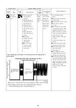
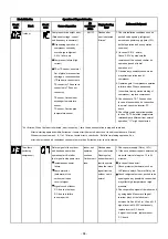
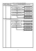
Compressor drive output error.
All OFF
Flashes after
(Relation of voltage, current
error is detected
and frequency is abnormal)
8
times*.
Overloading operation of
compressor caused by
over-charge refrigerant,
P.M.V. failure, etc.
Compressor failure (High
current).
1.
Check installation conditions such as
packed valve opening, refrigerant
amount and power supply (rate +10%,
both of operation and non operation
condition).
2. (In case of P.M.V. exists)
Check P.M.V. by measure the
resistance of the coil and confirm its
operation (sound of initial
operation, etc.)
3.
Observe any possibility cause which
may affect operation load of
compressor.
4.
Operate again. If compressor
operation
is failure when 20 seconds
passed
(count time from operation
starting of
compressor), replace
compressor.
*
4
or 8
times ; When first error is detected, error is count as 1 time, then once operation is stop and re-started.
After re-starting operation within 6 minutes, if same error is detected, error count is add (count become 2 times)
When error count comes 4, 8, 11 or 18 times, record error to check code. But after re-starting operation, if no
error is detected and air conditioner can operate more than 6 minutes, error count is cleared.
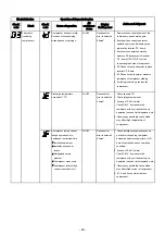
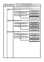
The others
Return signal of the outdoor
Indoor unit
Flashes when
(including
unit has been sent when
operates
error is detected.
compressor)
operation start. But after
continue.
Flashing stop
that, signal is stop some time.
Outdoor unit
and outdoor unit
Instantaneous power
stop.
start to operate
failure.
when the return
Some protector
signal from the
(hardware) of the
outdoor unit is
outdoor unit open
normal.
circuit of signal.
Signal circuit of indoor
P.C. board or outdoor
P.C. board is failure
in some period.
1.
Check power supply (Rate + 10%)
2.
If the air conditioner repeat operates
and
stop with interval of approx. 10
to
40
minutes.
(In case of
these
exist)
Check protector (hardware) such
as
Hi-Pressure switch,
Thermal-Relay, etc.
Check refrigerant amount, packed
valve
opening and any possibility
cause which
may affect high
temperature or high
pressure.
3.
Check operation signal of the indoor
unit
by using diode. Measure voltage
at
terminal block of the indoor unit
between No.2 and No.3 (or L2 and S)
If
signal is varied 15-60V continuously,
replace inverter P.C. board.
If signal is not varied, replace indoor
P.
C. board.
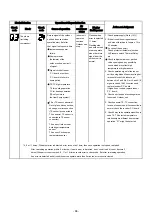
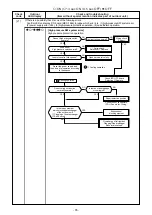
Action and Judgment
Outdoor
TE or TS sensor; abnormal.
Out of place, disconnection,
shortage, or misconnection
(TE sensor is connected to
TS connector, TS sensor is
connected to TE sensor
connector)
TE sensor; Outdoor heat
exchanger temperature
sensor
TS sensor; Suction pipe
temperature sensor
5.
Check sensors, TE, TS connection.
In
case of sensors and it’s connection
is
normal, check the inverter P
.
C
.
board
.
6.
Check 4way valve operation/position.
In case TE, TS detected temperature
relationship are different from normal
operation, “
1C
” might be detected.
- 64 -


