– 15 –
FILE NO. SVM-06017
7-2. Description of Operation Circuit
(1) When turning on the breaker, the operation lamp
blinks. This means that the power is on (or the
power supply is cut off.)
(2) When pressing [ ] button on the
remote control, receiving beep sounds from the
indoor unit, and the next operation is performed
together with opening the vertical air flow louver.
(3) Once the operation mode is set, it is memorized in
the microcomputer so that the previous operation
can be effected thereafter simply by pressing
[ ] button.
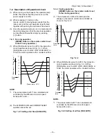
7-2-1. Fan only operation
([MODE] button on the remote control is set
to the fan only operation.)
(1) When [FAN] button is set to AUTO, the indoor fan
motor operates as shown in Fig. 7-2-1. When
[FAN] button is set to LOW, LOW
+
, MED, MED
+
or
HIGH, the motor operates with a constant air flow.
NOTE:
*1: The values marked with *1 are calculated and
controlled by the difference in motor speed
between M+ and L–.
7-2-2. Cooling operation
([MODE] button on the remote control is set
to the cooling operation.)
(1) The compressor, outdoor fan and operation
display on the remote control are controlled as
shown in Fig. 7-2-2.
Fig. 7-2-2
(2) When [FAN] button is set to AUTO, the indoor fan
motor operates as shown in Fig. 7-2-3. When
[FAN] button is set to LOW, LOW+, MED, MED+ or
HIGH, the motor operates with a constant air flow.
NOTE:
*1: The values marked with *1 are calculated and
controlled by the difference in motor speed
between M+ and L–.
Fig. 7-2-3 Setting of air flow [FAN:AUTO]
(Preset temp.: 24
°
C
+2
+2.5
+3
+1.5
+1
+0.5
0
M+
*1
*1
*1
L–
(Room temp.)
–
(Preset temp.)
Preset
temp.
0.5
0
Preset
temp.
ON
ON
OFF OFF OFF ON
Compressor
4-way valve
Outdoor fan
OPERATION
display
(Room temp.)
−
(Preset temp.)
*1
*1
*1
L–
+3
+2.5
+2
+1.5
+1
+0.5
-0.5
0
M+
(Room temp.)
–
(Preset temp.)
Preset
temp.
operation cannot be set.
Fig.
7-2-1 Setting of air flo
w [FAN:AUTO]
(2)
The Hi PO
WER, ECO and COMFORT SLEEP


