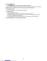
– 32 –
Item
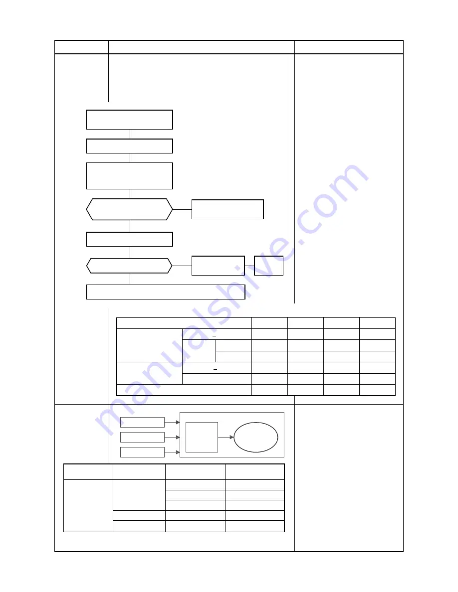
3. Outdoor fan
motor control
Operation flow and applicable data, etc.
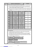
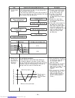
The blowing air volume at the outdoor unit side is controlled.
Receiving the operation command from the controller of indoor
unit, the controller of outdoor unit controls fan speed.
* For the fan motor, a DC motor with non-stage variable speed
system is used.
However, it is limited to 8 stages for reasons of controlling.
2) Fan speed
≥
400
when the motor stopped.
Air conditioner ON
(Remote controller)
YES
YES
NO
NO
Indoor unit controller
Fan motor ON
3) Fan lock
OFF status of
fan motor continues.
4) Motor operates as shown in the table below.
1) Outdoor unit
operation
command
(Outdoor
fan
control)
Air conditioner
OFF
Alarm
display
Description
1) The operation command sent
from the remote controller is
processed by the indoor unit
controller and transferred to the
controller of the outdoor unit.
2) When strong wind blows at
outdoor side, the operation of air
conditioner continues with the
fan motor stopped.
3) Whether the fan is locked or not
is detected, and the operation of
air conditioner stops and an
alarm is displayed if the fan is
locked.
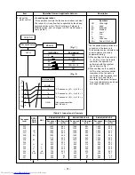
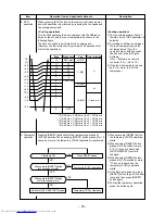
4) According to each operation
mode, by the conditions of
outdoor temperature (To) and
compressor revolution, the speed
of the outdoor fan shown in the
table is selected.
Cooling operation, dry operation
TO : Outdoor sensor
Compressor revolution (rps)
Outdoor temp. sensor
TO > 38°C
TO < 38°C
1 to 2 units
TO
1 to 2 units
Econo operation
TO > 38°C
TO < 38°C
TO is abnormal
20.3
~50.3
~62.8
63.4~
390 (rpm)
670 (rpm)
670 (rpm)
740 (rpm)
390 (rpm)
510 (rpm)
670 (rpm)
740 (rpm)
390 (rpm)
510 (rpm)
670 (rpm)
740 (rpm)
390 (rpm)
510 (rpm)
670 (rpm)
670 (rpm)
390 (rpm)
390 (rpm)
510 (rpm)
510 (rpm)
510 (rpm)
510 (rpm)
670 (rpm)
670 (rpm)
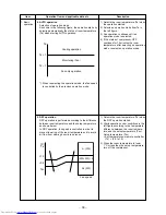
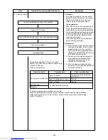
4. Capacity
control
1) Three indoor units from A to C
determine the respective
instruction revolutions from the
difference between the remote
controller setting temperature
(Ts) and the indoor temperature
(Ta), and transmit this to the
outdoor unit.
2) The outdoor unit receives the
instructions from the indoor
units, and the inverter operates
the compressor at the calculated
revolutions.
3) The compressor operation range
in each operating mode is shown
in the left table.
Indoor unit A
Inverter
Outdoor unit
Compressor
Indoor unit B
Indoor unit C
Operation mode
COOL
No.of
operating unit
1 unit
2 units
3 units
Combination
of indoor units
M10
M13
M16
¡
∗
¡
∗
Compressor
revolution (rps)
16 to 45
16 to 72
16 to 77
19 to 84
23 to 92
∗
: In case that any multiple indoor units are combined.
Summary of Contents for RAS-3M23GACV-E
Page 99: ... 99 MCC 1438 ...
Page 100: ... 100 MCC 818 ...


