– 83 –
10-4-7. Evacuating
After the piping has been connected to all indoor
unit(s), you can perform the air purge together at once.
AIR PURGE
Evacuate the air in the connecting pipes and in the
indoor unit using vacuum pump.
Do not use the refrigerant in the outdoor unit.
For details, see the manual of vacuum pump.
Use a vacuum pump
Be sure to use a vacuum pump with counter-flow
prevention function so that inside oil of the pump does
not flow backward into pipes of the air conditioner
when the pump stops.
(If inside oil of the vacuum pump enters into the air
conditioner which adopts R410A, a trouble of the
refrigeration cycle may be caused.)
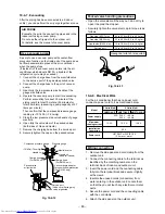
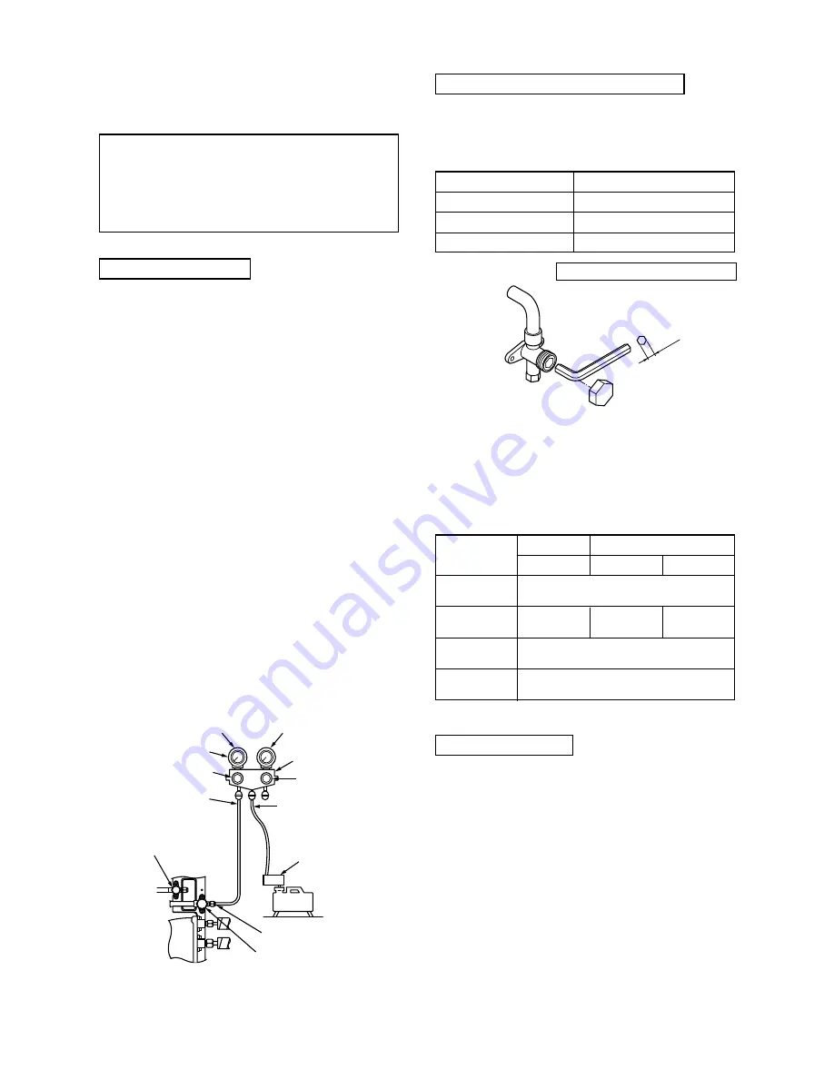
1. Connect the charge hose from the manifold valve
to the service port of the gas side packed valve.
2. Connect the charge hose to the port of vacuum
pump.
3. Open fully the low pressure side handle of the
gauge manifold valve.
4. Operate the vacuum pump to start for evacuating.
Perform evacuating for about 35 minutes if the
piping length is total 70 meters. (25 minutes for
total 50 meters) (assuming a pump capacity of 27
liters per minute.)
Then confirm that the compound pressure gauge
reading is –101 kPa ( –76 cmHg).
5. Close the low pressure side valve handle of gauge
manifold.
6. Open fully the valve stem of the packed valves
(both sides of Gas and Liquid).
7. Remove the charging hose from the service port.
8. Securely tighten the caps on the packed valves.
Packed valve handling precautions
• Open the valve stem all the way out ; do not try to
open it beyond the stopper.
• Securely tighten the valve stem cap in torque is as
follows :
Fig. 10-4-12
Fig. 10-4-13
10-4-8. Electrical Work
For the air conditioner that has no power cord,
connect a power cord to it as mentioned below.
Hexagonal wrench is required.
Model
Power supply
Maximum
running current
Installation
fuse rating
Power cord
3 Units Multi
4 Units Multi
3M26GAV-E
4M27GAV-E
4M27GACV-E
220 – 240 V
~
50 Hz
240 V
~
60 Hz
15.3 A
15.3 A
14.8 A
25 A
H07 RN-F or 245 IEC 66
(2.5 mm
2
or more)
Compound pressure gauge
Pressure gauge
Manifold valve
Handle Hi
(Keep full closed)
Charge hose
(For R410A only)
Vacuum pump adapter
for counter-flow prevention
(For R410A only)
Packed valve at gas side
Service port
(Valve core (Setting pin))
Handle Lo
Charge hose
(For R410A only)
–101kPa (–76cmHg)
Vacuum
pump
Packed valve
at liquid side
Gas side (Ø12.7 mm)
Gas side (Ø9.52 mm)
Liquid side (Ø6.35 mm)
Service port
50 to 62 N•m (5.0 to 6.2 kgf•m)
33 to 42 N•m (3.3 to 4.2 kgf•m)
14 to 18 N•m (1.4 to 1.8 kgf•m)
14 to 18 N•m (1.4 to 1.8 kgf•m)
4mm
Wiring connection
1. Remove the side panel and cord clamp from the
outdoor unit.
2. Connect the connecting cable to the terminal as
identified by the matching numbers on the
terminal block of indoor and outdoor unit.
3. Insert the power cord and the connecting cable
fully into the terminal block and secure it tightly
with screws.
4. Insulate the unused cords (conductors) from
water entering in the outdoor unit. Locate them
so that they do not touch any electrical or metal
parts.
5. Secure the power cord and the connecting cable
with the cord clamp.
6. Attach the side panel on the outdoor unit.
Summary of Contents for RAS-3M26GAV-E
Page 121: ... 121 MCC 1438 ...
Page 122: ... 122 MCC 818 ...

