background image

9. OPERATION DESCRIPTION

9-1. Outline of Air Conditioner Control

This air conditioner is a capacity-variable type air

conditioner, which uses DC motor for the indoor fan

motor and the outdoor fan motor. And the capacity-

proportional control compressor which can change the

motor speed in the range from 12 to 100 rps is mounted.
The DC motor drive circuit is mounted to the indoor

unit. The compressor and the inverter to control fan

motor are mounted to the outdoor unit.
The entire air conditioner is mainly controlled by the

indoor unit controller.
The indoor unit controller drives the indoor fan motor

based upon command sent from the remote controller,

and transfers the operation command to the outdoor

unit controller.
The outdoor unit controller receives operation

command from the indoor unit side, and controls the

outdoor fan and the pulse motor valve. (PMV)
Besides, detecting revolution position of the

compressor motor, the outdoor unit controller controls

speed of the compressor motor by controlling output

voltage of the inverter and switching timing of the

supply power (current transfer timing) so that motors

drive according to the operation command.
And then, the outdoor unit controller transfers reversely

the operating status information of the outdoor unit to

control the indoor unit controller.

Operations followed to judgment of

serial signal from indoor side.

• Detection of inverter input current and current

release operation

• Over-current detection and prevention operation

to IGBT module (Compressor stop function)

• Compressor and outdoor fan stop function when

serial signal is off (when the serial signal does not

reach the board assembly of outdoor control by

trouble of the signal system)

• Transferring of operation information (Serial

signal) from outdoor unit controller to indoor unit

controller

• Detection of outdoor temperature and operation

revolution control

• Defrost control in heating operation

(Temp. measurement by outdoor heat exchanger

and control for 4-way valve and outdoor fan)

3. Contents of operation command signal

(Serial signal) from indoor unit controller to

outdoor unit controller

The following three types of signals are sent from

the indoor unit controller.
• Operation mode set on the remote controller
• Compressor revolution command signal defined

by indoor temperature and set temperature

(Correction along with variation of room

temperature and correction of indoor heat

exchanger temperature are added.)

• Temperature of indoor heat exchanger
• For these signals ([Operation mode] and

[Compressor revolution] indoor heat exchanger

temperature), the outdoor unit controller monitors

the input current to the inverter, and performs the

followed operation within the range that current

does not exceed the allowable value.

4. Contents of operation command signal

(Serial signal) from outdoor unit controller

to indoor unit controller

The following signals are sent from the outdoor unit

controller.
• The current operation mode
• The current compressor revolution
• Outdoor temperature
• Existence of protective circuit operation

For transferring of these signals, the indoor unit

controller monitors the contents of signals, and

judges existence of trouble occurrence.
Contents of judgment are described below.
• Whether distinction of the current operation

status meets to the operation command signal

• Whether protective circuit operates

When no signal is received from the outdoor

unit controller, it is assumed as a trouble.

As the compressor adopts four-pole brushless DC

motor, the frequency of the supply power from

inverter to compressor is two-times cycles of the

actual number of revolution.

1. Role of indoor unit controller

The indoor unit controller judges the operation

commands from the remote controller and assumes

the following functions.
• Judgment of suction air temperature of the indoor

heat exchanger by using the indoor temp. sensor.

(TA sensor)

• Judgment of the indoor heat exchanger

temperature by using heat exchanger sensor

(TC sensor) (Prevent-freezing control, etc.)

• Louver motor control
• Indoor fan motor operation control
• LED (Light Emitting Diode) display control
• Transferring of operation command signal

(Serial signal) to the outdoor unit

• Reception of information of operation status

(Serial signal including outside temp. data) to the

outdoor unit and judgment/display of error

• Air purifier operation control

2. Role of outdoor unit controller

Receiving the operation command signal

(Serial signal) from the indoor unit controller, the

outdoor unit performs its role.
• Compressor operation control
• Operation control of outdoor fan motor
• P.M.V. control
• 4-way valve control

FILE NO. SVM-15073

- 50 -

Summary of Contents for RAS-4M27S3AV-A

Page 1: ...R410A SERVICE MANUAL AIR CONDITIONER SPLIT TYPE RAS 4M27S3AV E RAS 4M27S3AV A RAS 4M27S3AV TR July 2015 FILE NO SVM 15073 ...

Page 2: ... WIRING DIAGRAM 36 6 SPECIFICATIONS OF ELECTRICAL PARTS 38 7 REFRIGERANT CYCLE DIAGRAM 39 8 CONTROL BLOCK DIAGRAM 46 9 OPERATION DESCRIPTION 48 10 INSTALLATION PROCEDURE 74 11 HOW TO DIAGNOSE THE TROUBLE 93 12 HOW TO REPLACE THE MAIN PARTS 121 13 EXPLODED VIEWS AND PARTS LIST 107 FILE NO SVM 15073 2 ...

Page 3: ... conditioner circuit To prevent mixing of refrigerant or refrigerating machine oil the sizes of connecting sections of charging port on main unit and installation tools are different from those used for the conventional refrigerant units Accordingly special tools are required for the new refrigerant R410A units For connecting pipes use new and clean piping materials with high pressure fittings mad...

Page 4: ...CUIT IF AIR OR ANY OTHER GAS IS MIXED IN THE REFRIGERANT THE GAS PRESSURE IN THE REFRIGERATION CIRCUIT WILL BECOME ABNORMALLY HIGH AND IT MAY RESULT IN THE PIPE BURSTING AND POSSIBLE PERSONNEL INJURIES IN THE EVENT THAT THE REFRIGERANT GAS LEAKS OUT OF THE PIPE DURING THE SERVICE WORK AND THE INSTALLATION WORK IMMEDIATELY LET FRESH AIR INTO THE ROOM IF THE REFRIGERANT GAS IS HEATED SUCH AS BY FIRE...

Page 5: ...Hz Cooling Heating 10 94 10 46 10 03 9 22 8 82 8 45 2286 1927 95 95 10 94 10 46 10 03 3 50 4 67 48 49 890 900 320 72 2000 Twin rotary type with DC inverter variable speed control DA220A2T 20LD 60 High 2507 Medium 2507 Flare connection Ø6 35 Ø12 7 Ø6 35 Ø12 7 Ø6 35 Ø9 52 Ø6 35 Ø9 52 25 70 40 15 R410A 2 40 3 Wires includes earth 4 Wires includes earth 10 to 46 15 to 24 4M27S3AV E A TR 1 2 SPECIFICAT...

Page 6: ...p DRED terminal block connections Banding band These models supports DRM1 DRM2 DRM3 1 E30m total electrical energy kWh used by the air conditioner for all purposes including compressors controls and fans over a 30 min period 2 R rated input electrical power of the air conditioner kW at rated capacity in the mode in which it is operating during the demand response event i e cooling or heating DRED ...

Page 7: ...response P C board MCC 1653 2 Transformer TT 02 AC230 240V 50Hz AC230V 50 60Hz 150mA DRC signal transmission connector CN105 DRC signal reception connector CN01 Transformer input connector CN101 Power supply protection fuse F100 250V 3 15A Power supply input connector CN100 Transformer output connector CN102 DB100 LED indicator D101 FILE NO SVM 15073 7 ...

Page 8: ... 2 21 6 3 2 9 6 9 2040 670 2400 9 76 3 81 11 13 48 63 22 10 4 69 2 11 6 8 3 0 7 2 2320 690 2570 11 10 3 92 11 92 48 63 24 10 5 22 1 98 7 2 3 2 7 5 2550 700 2750 12 20 3 98 12 76 48 63 13 13 3 15 3 15 6 3 2 9 6 9 2040 670 2400 9 76 3 81 11 13 48 63 16 13 3 73 3 07 6 8 3 0 7 2 2320 690 2570 11 10 3 92 11 92 48 63 18 13 3 91 2 89 6 8 3 0 7 2 2320 690 2570 11 10 3 92 11 92 48 63 22 13 4 45 2 75 7 2 3 ...

Page 9: ... 3 2410 960 2740 11 53 4 85 12 71 48 63 16 10 10 3 50 2 10 2 10 7 7 4 0 8 5 2410 960 2790 11 53 4 85 12 94 48 63 18 10 10 3 70 2 00 2 00 7 7 4 0 8 5 2410 960 2790 11 53 4 85 12 94 48 63 22 10 10 4 16 1 87 1 87 7 9 4 1 8 7 2440 970 2830 11 67 4 90 13 13 48 63 24 10 10 4 49 1 71 1 71 7 9 4 1 8 7 2440 970 2830 11 67 4 90 13 13 48 63 13 13 10 2 82 2 82 2 06 7 7 4 0 8 5 2410 960 2790 11 53 4 85 12 94 4...

Page 10: ... 76 2 27 1 65 1 22 7 9 4 2 9 3 2257 950 2820 10 80 4 80 13 08 48 63 18 13 10 07 2 95 2 18 1 59 1 18 7 9 4 2 9 3 2257 950 2820 10 80 4 80 13 08 48 63 22 13 10 07 3 33 2 06 1 50 1 11 8 0 4 2 9 3 2286 950 2820 10 94 4 80 13 08 48 63 24 13 10 07 3 66 1 91 1 39 1 03 8 0 4 2 9 3 2286 950 2820 10 94 4 80 13 08 48 63 16 16 10 07 2 59 2 59 1 56 1 15 7 9 4 2 9 3 2257 950 2820 10 80 4 80 13 08 48 63 18 16 10...

Page 11: ...40 670 2400 9 34 3 64 10 65 48 63 22 10 4 69 2 11 6 8 3 0 7 2 2320 690 2570 10 62 3 75 11 40 48 63 24 10 5 22 1 98 7 2 3 2 7 5 2550 700 2750 11 67 3 80 12 20 48 63 13 13 3 15 3 15 6 3 2 9 6 9 2040 670 2400 9 34 3 64 10 65 48 63 16 13 3 73 3 07 6 8 3 0 7 2 2320 690 2570 10 62 3 75 11 40 48 63 18 13 3 91 2 89 6 8 3 0 7 2 2320 690 2570 10 62 3 75 11 40 48 63 22 13 4 45 2 75 7 2 3 2 7 5 2550 700 2750 ...

Page 12: ... 4 64 12 38 48 63 22 10 10 4 16 1 87 1 87 7 9 4 1 8 7 2440 970 2830 11 17 4 69 12 56 48 63 24 10 10 4 49 1 71 1 71 7 9 4 1 8 7 2440 970 2830 11 17 4 69 12 56 48 63 13 13 10 2 82 2 82 2 06 7 7 4 0 8 5 2410 960 2790 11 03 4 64 12 38 48 63 16 13 10 3 22 2 65 1 93 7 8 4 1 8 6 2430 970 2810 11 12 4 69 12 47 48 63 18 13 10 3 42 2 53 1 85 7 8 4 1 8 6 2430 970 2810 11 12 4 69 12 47 48 63 22 13 10 3 82 2 3...

Page 13: ...2 27 1 65 1 22 7 9 4 2 9 3 2257 950 2820 10 33 4 59 12 51 48 63 18 13 10 07 2 95 2 18 1 59 1 18 7 9 4 2 9 3 2257 950 2820 10 33 4 59 12 51 48 63 22 13 10 07 3 33 2 06 1 50 1 11 8 0 4 2 9 3 2286 950 2820 10 46 4 59 12 51 48 63 24 13 10 07 3 66 1 91 1 39 1 03 8 0 4 2 9 3 2286 950 2820 10 46 4 59 12 51 48 63 16 16 10 07 2 59 2 59 1 56 1 15 7 9 4 2 9 3 2257 950 2820 10 33 4 59 12 51 48 63 18 16 10 07 ...

Page 14: ...40 670 2400 8 95 3 49 10 20 48 63 22 10 4 69 2 11 6 8 3 0 7 2 2320 690 2570 10 18 3 59 10 93 48 63 24 10 5 22 1 98 7 2 3 2 7 5 2550 700 2750 11 18 3 65 11 69 48 63 13 13 3 15 3 15 6 3 2 9 6 9 2040 670 2400 8 95 3 49 10 20 48 63 16 13 3 73 3 07 6 8 3 0 7 2 2320 690 2570 10 18 3 59 10 93 48 63 18 13 3 91 2 89 6 8 3 0 7 2 2320 690 2570 10 18 3 59 10 93 48 63 22 13 4 45 2 75 7 2 3 2 7 5 2550 700 2750 ...

Page 15: ... 4 44 11 86 48 63 22 10 10 4 16 1 87 1 87 7 9 4 1 8 7 2440 970 2830 10 70 4 49 12 03 48 63 24 10 10 4 49 1 71 1 71 7 9 4 1 8 7 2440 970 2830 10 70 4 49 12 03 48 63 13 13 10 2 82 2 82 2 06 7 7 4 0 8 5 2410 960 2790 10 57 4 44 11 86 48 63 16 13 10 3 22 2 65 1 93 7 8 4 1 8 6 2430 970 2810 10 66 4 49 11 95 48 63 18 13 10 3 42 2 53 1 85 7 8 4 1 8 6 2430 970 2810 10 66 4 49 11 95 48 63 22 13 10 3 82 2 3...

Page 16: ... 1 65 1 22 7 9 4 2 9 3 2257 950 2820 9 90 4 40 11 99 48 63 18 13 10 07 2 95 2 18 1 59 1 18 7 9 4 2 9 3 2257 950 2820 9 90 4 40 11 99 48 63 22 13 10 07 3 33 2 06 1 50 1 11 8 0 4 2 9 3 2286 950 2820 10 03 4 40 11 99 48 63 24 13 10 07 3 66 1 91 1 39 1 03 8 0 4 2 9 3 2286 950 2820 10 03 4 40 11 99 48 63 16 16 10 07 2 59 2 59 1 56 1 15 7 9 4 2 9 3 2257 950 2820 9 90 4 40 11 99 48 63 18 16 10 07 2 78 2 ...

Page 17: ...4 74 3 16 7 9 1 5 10 1 2480 320 3230 11 87 1 94 14 98 49 64 22 10 5 28 3 02 8 3 1 5 10 2 2700 320 3240 12 92 1 94 15 03 49 64 24 10 5 76 2 84 8 6 1 5 10 2 2860 320 3250 13 68 1 94 15 07 49 64 13 13 3 95 3 95 7 9 1 5 10 1 2480 320 3230 11 87 1 94 14 98 49 64 16 13 4 35 3 95 8 3 1 5 10 2 2700 320 3240 12 92 1 94 15 03 49 64 18 13 4 53 3 77 8 3 1 5 10 2 2700 320 3240 12 92 1 94 15 03 49 64 22 13 5 02...

Page 18: ...24 2 16 12 80 49 64 22 10 10 4 15 2 37 2 37 8 9 2 0 10 7 2450 380 2790 11 72 2 16 12 94 49 64 24 10 10 4 48 2 21 2 21 8 9 2 0 10 7 2450 380 2790 11 72 2 16 12 94 49 64 13 13 10 3 11 3 11 2 49 8 7 2 0 10 5 2350 380 2760 11 24 2 16 12 80 49 64 16 13 10 3 34 3 03 2 43 8 8 2 0 10 6 2400 380 2780 11 48 2 16 12 89 49 64 18 13 10 3 56 2 97 2 37 8 9 2 0 10 7 2450 380 2790 11 72 2 16 12 94 49 64 22 13 10 3...

Page 19: ...85 2 59 2 07 1 40 8 9 2 9 11 7 1905 501 2600 9 11 2 53 12 06 49 64 18 13 10 07 3 02 2 51 2 01 1 36 8 9 2 9 11 7 1905 501 2600 9 11 2 53 12 06 49 64 22 13 10 07 3 37 2 41 1 93 1 30 9 0 2 6 11 7 1927 480 2600 9 22 2 42 12 06 49 64 24 13 10 07 3 68 2 27 1 82 1 23 9 0 2 6 11 7 1927 480 2600 9 22 2 42 12 06 49 64 16 16 10 07 2 77 2 77 2 01 1 36 8 9 2 9 11 7 1905 501 2600 9 11 2 53 12 06 49 64 18 16 10 ...

Page 20: ... 5 10 1 2480 320 3230 11 35 1 86 14 33 49 64 22 10 5 28 3 02 8 3 1 5 10 2 2700 320 3240 12 36 1 86 14 37 49 64 24 10 5 76 2 84 8 6 1 5 10 2 2860 320 3250 13 09 1 86 14 42 49 64 13 13 3 95 3 95 7 9 1 5 10 1 2480 320 3230 11 35 1 86 14 33 49 64 16 13 4 35 3 95 8 3 1 5 10 2 2700 320 3240 12 36 1 86 14 37 49 64 18 13 4 53 3 77 8 3 1 5 10 2 2700 320 3240 12 36 1 86 14 37 49 64 22 13 5 02 3 58 8 6 1 5 1...

Page 21: ...76 2 07 12 24 49 64 22 10 10 4 15 2 37 2 37 8 9 2 0 10 7 2450 380 2790 11 21 2 07 12 38 49 64 24 10 10 4 48 2 21 2 21 8 9 2 0 10 7 2450 380 2790 11 21 2 07 12 38 49 64 13 13 10 3 11 3 11 2 49 8 7 2 0 10 5 2350 380 2760 10 76 2 07 12 24 49 64 16 13 10 3 34 3 03 2 43 8 8 2 0 10 6 2400 380 2780 10 98 2 07 12 33 49 64 18 13 10 3 56 2 97 2 37 8 9 2 0 10 7 2450 380 2790 11 21 2 07 12 38 49 64 22 13 10 3...

Page 22: ...85 2 59 2 07 1 40 8 9 2 9 11 7 1905 501 2600 8 72 2 42 11 54 49 64 18 13 10 07 3 02 2 51 2 01 1 36 8 9 2 9 11 7 1905 501 2600 8 72 2 42 11 54 49 64 22 13 10 07 3 37 2 41 1 93 1 30 9 0 2 6 11 7 1927 480 2600 8 82 2 32 11 54 49 64 24 13 10 07 3 68 2 27 1 82 1 23 9 0 2 6 11 7 1927 480 2600 8 82 2 32 11 54 49 64 16 16 10 07 2 77 2 77 2 01 1 36 8 9 2 9 11 7 1905 501 2600 8 72 2 42 11 54 49 64 18 16 10 ...

Page 23: ... 10 1 2480 320 3230 10 88 1 78 13 73 49 64 22 10 5 28 3 02 8 3 1 5 10 2 2700 320 3240 11 84 1 78 13 78 49 64 24 10 5 76 2 84 8 6 1 5 10 2 2860 320 3250 12 54 1 78 13 82 49 64 13 13 3 95 3 95 7 9 1 5 10 1 2480 320 3230 10 88 1 78 13 73 49 64 16 13 4 35 3 95 8 3 1 5 10 2 2700 320 3240 11 84 1 78 13 78 49 64 18 13 4 53 3 77 8 3 1 5 10 2 2700 320 3240 11 84 1 78 13 78 49 64 22 13 5 02 3 58 8 6 1 5 10 ...

Page 24: ...31 1 98 11 73 49 64 22 10 10 4 15 2 37 2 37 8 9 2 0 10 7 2450 380 2790 10 75 1 98 11 86 49 64 24 10 10 4 48 2 21 2 21 8 9 2 0 10 7 2450 380 2790 10 75 1 98 11 86 49 64 13 13 10 3 11 3 11 2 49 8 7 2 0 10 5 2350 380 2760 10 31 1 98 11 73 49 64 16 13 10 3 34 3 03 2 43 8 8 2 0 10 6 2400 380 2780 10 53 1 98 11 82 49 64 18 13 10 3 56 2 97 2 37 8 9 2 0 10 7 2450 380 2790 10 75 1 98 11 86 49 64 22 13 10 3...

Page 25: ...85 2 59 2 07 1 40 8 9 2 9 11 7 1905 501 2600 8 36 2 32 11 05 49 64 18 13 10 07 3 02 2 51 2 01 1 36 8 9 2 9 11 7 1905 501 2600 8 36 2 32 11 05 49 64 22 13 10 07 3 37 2 41 1 93 1 30 9 0 2 6 11 7 1927 480 2600 8 45 2 22 11 05 49 64 24 13 10 07 3 68 2 27 1 82 1 23 9 0 2 6 11 7 1927 480 2600 8 45 2 22 11 05 49 64 16 16 10 07 2 77 2 77 2 01 1 36 8 9 2 9 11 7 1905 501 2600 8 36 2 32 11 05 49 64 18 16 10 ...

Page 26: ... 50 60 70 80 Total pipe length m Heating capacity ratio Conditions Indoor DB20 C Outdoor DB7 C WB6 C Indoor air flow High 4 units operating Standard pipe length 25m Standard pipe length 25m 2 3 1 Operation Characteristic Curve Cooling Heating 2 3 3 Capacity Variation Ratio According to Pipe Length Cooling Heating 2 3 2 Capacity Variation Ratio According to Outdoor Temperature Cooling Heating 30 0 ...

Page 27: ...n the refrigeration cycle may become abnormally high so that a rupture or personal injury may be caused 5 After completion of installation work check to make sure that there is no refrigeration gas leakage If the refrigerant gas leaks into the room coming into contact with fire in the fan driven heater space heater etc a poisonous gas may occur 6 When an air conditioning system charged with a larg...

Page 28: ...r or dust does not enter the pipe interior that no other oil than lubricating oils used in the installed air water heat pump is used and that refrigerant does not leak When using lubricating oils in the piping processing use such lubricating oils whose water content has been removed When stored be sure to seal the container with an airtight cap or any other cover 1 Flare processing procedures and ...

Page 29: ...Outer diameter mm 6 35 9 52 12 70 15 88 Thickness mm 0 8 0 8 0 8 1 0 A mm Flare tool for R410A Conventional flare tool clutch type Clutch type Wing nut type 0 to 0 5 1 0 to 1 5 1 5 to 2 0 0 to 0 5 1 0 to 1 5 1 5 to 2 0 0 to 0 5 1 0 to 1 5 2 0 to 2 5 0 to 0 5 1 0 to 1 5 2 0 to 2 5 Nominal diameter 1 4 3 8 1 2 5 8 Outer diameter mm 6 35 9 52 12 70 15 88 Thickness mm 0 8 0 8 0 8 1 0 A mm Flare tool f...

Page 30: ...que for R410A is the same as that for conventional R22 Incidentally when the torque is weak the gas leakage may occur When it is strong the flare nut may crack and may be made non removable When choosing the tightening torque comply with values designated by manufacturers Table 3 2 7 shows reference values NOTE When applying oil to the flare surface be sure to use oil designated by the manufacture...

Page 31: ...ng currently developed General tools Conventional tools can be used In addition to the above exclusive tools the following equipments which serve also for R22 are necessary as the general tools 1 Vacuum pump 7 Screwdriver Use vacuum pump by attaching vacuum pump adapter 8 Spanner or Monkey wrench 2 Torque wrench For Ø6 35 Ø9 52 9 Hole core drill Ø65 3 Pipe cutter 10 Hexagon wrench Opposite side 4m...

Page 32: ...nnecting port of the electronic balance and charge liquid refrigerant Outdoor unit Indoor unit Opened Opened Refrigerant cylinder with siphon Check valve Open close valve for charging Electronic balance for refrigerant charging Opened Closed Service port 3 4 Recharging of Refrigerant When it is necessary to recharge refrigerant charge the specified amount of new refrigerant according to the follow...

Page 33: ...silver and copper It is used to join iron copper or copper alloy and is relatively expensive though it excels in solderability 2 Phosphor bronze brazing filler Phosphor bronze brazing filler is generally used to join copper or copper alloy 3 Low temperature brazing filler Low temperature brazing filler is generally called solder and is an alloy of tin and lead Since it is weak in adhesive strength...

Page 34: ...x which does not contain chlorine 3 When adding water to the flux use water which does not contain chlorine e g distilled water or ion exchange water 4 Remove the flux after brazing 3 5 3 Brazing As brazing work requires sophisticated techniques experiences based upon a theoretical knowledge it must be performed by a person qualified In order to prevent the oxide film from occurring in the pipe in...

Page 35: ...or bolt B leg part Hanger Fan guard Mounting hole sold separately 12 dia 3 emboss 5 drain long hole dia 20 88 Drain hole dia 25 Knock out Gas valve Service part Liquid valve Connecting pipe port Connecting pipe dia 6 35 Connecting pipe dia 9 52 Connecting pipe dia 6 35 Connecting pipe dia 9 52 Connecting pipe dia 6 35 Connecting pipe dia 12 7 Connecting pipe dia 6 35 Connecting pipe dia 12 7 D uni...

Page 36: ...5 1 Outdoor Unit RAS 4M27S3AV A 5 WIRING DIAGRAM FILE NO SVM 15073 36 ...

Page 37: ... F TD TO TE PMV Symbol BLU BLUE BLK BLACK COLOR IDENTIFICATION RED RED Part name PULSE MOTOR VALVE DISCHARGE PIPE TEMP SENSOR CONDENSER PIPE TEMP SENSOR OUTDOOR TEMP SENSOR SUCTION PIPE TEMP SENSOR GAS SIDE PIPE TEMP SENSOR A D LINE FILTER GRN GREEN WHI WHITE YEL YELLOW ...

Page 38: ... demand connecting wires and relay connector RJ45 so that they do not come into contact with the refrigerant cycle parts or refrigerant pipes Wire breakage or water intrusion may cause electric shock or fire Do not screw the DRED signal receiver directly to the outdoor unit The screw may damage the internal parts and cause an electric shock fire or refrigerant leak CAUTION Wear heavy gloves during...

Page 39: ...ng during the demand response event i e cooling or heating Wiring procedure 1 Securely fasten the demand connecting wires with the cord clamp located at the upper portion of the terminal block so that no external force is applied to the terminal The demand connecting wires having a relay connector RJ45 should be wired in such a manner as to prevent water intrusion into the relay connector 2 Bundle...

Page 40: ...scharge temp sensor Td sensor Suction temp sensor Ts sensor Temp sensor at A room gas side TGa sensor Temp sensor at B room gas side TGb sensor Temp sensor at C room gas side TGc sensor Temp sensor at D room gas side TGd sensor Compressor thermo Terminal block 9P Model name DA220A2T 20LD ICF 280 A60 1 CH 56 3Z T CH 76 TM1 5TF H01AP1874A1 UKV A039 MCC 1571 MCC 5071 MCC 1436 CS 12AL Rating Output 60...

Page 41: ...ping length is 40m or less If the length exceeds 41m add 20g of refrigerant per 1 meter over Connection of only one indoor unit is unavailable Two or more indoor units should be connected DA220A2T 20LD Outdoor unit tank 1500cc 2 3 450Lx2 2 3 550Lx1 2 3 600Lx1 2 40kg R410A FILE NO SVM 15073 41 ...

Page 42: ...gh High 62 2 24 13 0 7 to 0 9 9 to 11 51 to 53 High High 62 2 16 16 0 7 to 0 9 9 to 11 52 to 54 High High 62 2 18 16 0 7 to 0 9 9 to 11 52 to 54 High High 62 2 22 16 0 7 to 0 9 9 to 11 52 to 54 High High 62 2 24 16 0 7 to 0 9 9 to 11 52 to 54 High High 62 2 18 18 0 7 to 0 9 9 to 11 52 to 54 High High 62 2 22 18 0 7 to 0 9 9 to 11 52 to 54 High High 62 2 24 18 0 7 to 0 9 9 to 11 52 to 54 High High ...

Page 43: ...0 11 to 13 51 to 53 High High 59 8 24 13 13 0 8 to 1 0 11 to 13 51 to 53 High High 59 8 16 16 13 0 8 to 1 0 11 to 13 51 to 53 High High 59 8 18 16 13 0 8 to 1 0 11 to 13 51 to 53 High High 59 8 22 16 13 0 8 to 1 0 11 to 13 51 to 53 High High 59 8 24 16 13 0 8 to 1 0 11 to 13 51 to 53 High High 59 8 18 18 13 0 8 to 1 0 11 to 13 51 to 53 High High 59 8 22 18 13 0 8 to 1 0 11 to 13 51 to 53 High High...

Page 44: ... High 62 2 16 13 13 07 1 0 to 1 2 15 to 17 51 to 53 High High 62 2 18 13 13 07 1 0 to 1 2 15 to 17 51 to 53 High High 62 2 16 16 13 07 1 0 to 1 2 15 to 17 51 to 53 High High 62 2 18 16 13 07 1 0 to 1 2 15 to 17 51 to 53 High High 62 2 10 10 10 10 1 0 to 1 2 15 to 17 51 to 53 High High 62 2 13 10 10 10 1 0 to 1 2 15 to 17 51 to 53 High High 62 2 16 10 10 10 1 0 to 1 2 15 to 17 51 to 53 High High 62...

Page 45: ...3 48 to 50 1 to 1 High High 71 2 16 16 3 1 to 3 3 48 to 50 1 to 1 High High 71 2 18 16 3 1 to 3 3 48 to 50 1 to 1 High High 71 2 22 16 3 1 to 3 3 48 to 50 1 to 1 High High 71 2 24 16 3 1 to 3 3 48 to 50 1 to 1 High High 71 2 18 18 3 1 to 3 3 48 to 50 1 to 1 High High 71 2 22 18 3 1 to 3 3 48 to 50 1 to 1 High High 71 2 24 18 3 1 to 3 3 48 to 50 1 to 1 High High 71 2 3 units 07 07 07 2 3 to 2 5 38 ...

Page 46: ... 39 2 to 0 High High 73 0 16 16 13 2 5 to 2 7 37 to 39 2 to 0 High High 73 0 18 16 13 2 5 to 2 7 37 to 39 2 to 0 High High 73 0 22 16 13 2 5 to 2 7 37 to 39 2 to 0 High High 73 0 24 16 13 2 5 to 2 7 37 to 39 2 to 0 High High 73 0 18 18 13 2 5 to 2 7 37 to 39 2 to 0 High High 73 0 22 18 13 2 5 to 2 7 37 to 39 2 to 0 High High 73 0 16 16 16 2 5 to 2 7 37 to 39 2 to 0 High High 73 0 22 16 16 2 5 to 2...

Page 47: ...4 33 to 35 2 to 0 High High 73 0 18 13 13 07 2 2 to 2 4 33 to 35 2 to 0 High High 73 0 16 16 13 07 2 2 to 2 4 33 to 35 2 to 0 High High 73 0 18 16 13 07 2 2 to 2 4 33 to 35 2 to 0 High High 73 0 10 10 10 10 2 2 to 2 4 33 to 35 2 to 0 High High 73 0 13 10 10 10 2 2 to 2 4 33 to 35 2 to 0 High High 73 0 16 10 10 10 2 2 to 2 4 33 to 35 2 to 0 High High 73 0 18 10 10 10 2 2 to 2 4 33 to 35 2 to 0 High...

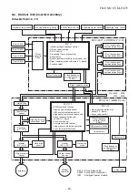
Page 48: ...B Transformer High power factor correction circuit Converter AC DC Gate drive circuit Inverter DC AC Converter AC DC Output current sensor Output current sensor Input current sensor D unit serial signal communication circuit C unit serial signal communication circuit B unit serial signal communication circuit A unit serial signal communication circuit Clock frequency oscillator circuit 20 MHz Cloc...

Page 49: ...nverter AC DC Gate drive circuit Inverter DC AC Output current sensor Output current sensor Input current sensor D unit serial signal communication circuit C unit serial signal communication circuit B unit serial signal communication circuit A unit serial signal communication circuit Clock frequency oscillator circuit 20 MHz Gate drive circuit Inverter DC AC Signal communication with control P C b...

Page 50: ...mode set on the remote controller Compressor revolution command signal defined by indoor temperature and set temperature Correction along with variation of room temperature and correction of indoor heat exchanger temperature are added Temperature of indoor heat exchanger For these signals Operation mode and Compressor revolution indoor heat exchanger temperature the outdoor unit controller monitor...

Page 51: ...5 Winding Coil heating control 56 6 Defrost control Only in heating operation 56 7 Compressor protective control 56 8 Discharge temperature control 57 9 Pulse motor valve PMV control 57 9 3 Intermittent Operation Control for Indoor Fans of the Indoor Unit at Thermo off Side in Heating Operation 58 10 High pressure switch Compressor case thermostat control 57 11 Various setting on outdoor unit Powe...

Page 52: ...operation function Compressor Outdoor fan motor 4 way valve Pulse motor valve P M V Signal receiving Indoor unit control Operation command Serial signal send receive Selection of operation conditions ON OFF Serial signal send receive Outdoor unit control Inverter Item 1 Basic operation Operation flow and applicable data etc 1 Operation control Receiving the user s operation condition setup the ope...

Page 53: ... the operation signal sent from the indoor unit 1 The relay of 4 way valve is turned on for a few seconds when 4 way valve is driven Description No 1 2 3 4 5 6 7 8 9 10 11 12 13 14 15 16 Indoor unit Pushed first Pushed last Pushed first Pushed last Pushed first Pushed last Pushed first Pushed last Pushed first Pushed last Pushed first Pushed last Pushed first Pushed last Pushed first Pushed last P...

Page 54: ...peration of air conditioner continues with the fan motor stopped 3 Whether the fan is locked or not is detected and the operation of air conditioner stops and an alarm is displayed if the fan is locked 4 According to each operation mode by the conditions of outdoor temperature To and compressor revolution the speed of the outdoor fan shown in the table is selected Cooling operation dry operation 1...

Page 55: ... compressor at the calculated revolutions 3 The compressor operation range in each operating mode is shown in the left table 1 The input current of the outdoor unit is detected in the inverter section of the outdoor unit 2 According to the detected outdoor temperature the specified value of the current is selected 3 Whether the current value exceeds the specified value or not is judged 4 If the cu...

Page 56: ...ntinue Description Winding Coil heating is performed when the following conditions are met Condition 1 When the discharge sensor temperature Td is less than 30 C Condition 2 When the outdoor sensor temperature To is as shown in the left figure The necessity of defrost operation is detected by the outdoor heat exchanger temperature The conditions to detect the necessity of defrost operation differ ...

Page 57: ...nt SH control 3 If the discharge temperature was excessively up adjust the open degree of valve so that it is in the range of set temperature Discharge temp control 4 When defrost operation is performed the open degree of PMV is adjusted according to each setup conditions during preparation for defrost and during defrost operation 4 way valve is inversed 5 When turning off the compressor by thermo...

Page 58: ...p number of revolution 1 Operated with UL or SUL Fan stop T off T off T off T on T on T on UL 1 UL 1 UL 1 Fan stop Fan stop In case which Tc sensor temperature exceeds 55 C in B room the fan stops intermittent operation and starts continuous operation with UL or SUL 1 2 min 3 min 4 min To 5 C 5 To 10 10 To T off time Item Operation flow and applicable data etc Description The following settings ar...

Page 59: ...0A Gauge manifold Charge hose Electronic balance for refrigerant charging Torque wrench nominal diam 1 2 5 8 Flare tool clutch type Gauge for projection adjustment Vacuum pump adapter Gas leakage detector Applicable to R22 model Changes As pressure is high it is impossible to measure by means of conventional gauge In order to prevent any other refrigerant from being charged each port diameter has ...

Page 60: ...ng blocking the air discharging 2 When the outdoor unit is installed in a place exposed always to a strong wind like a coast or on a high story of a building secure the normal fan operation using a duct or a wind shield 3 Especially in windy area install the unit to prevent the admission of wind Fig 10 2 1 4 Installation in the following places may result in trouble Do not install the unit in such...

Page 61: ...low Total piping length Non Additional refrigerant 40 m Additional refrigerant 70 m 41 to 70 m Additional 20 g of refrigerant Per every 1 m Minimum piping length A or B or C or D 3 m or more Maximum indoor piping length A or B or C or D 25 m or less Maximum piping height difference A or B or C or D 15 m or less Maximum piping height difference between 2 units 15 m or less Fig 10 2 5 4 Connect 2 or...

Page 62: ...wnward Tightening torque of flare pipe The pressure of R410A is higher than R22 Approx 1 6 times Therefore securely tighten the flare pipes which connect the outdoor unit and indoor unit with the specified tightening torque using a torque wrench If any flare pipe is incorrectly connected it may cause not only a gas leakage but also trouble in the refrigeration cycle Fig 10 2 7 Fig 10 2 8 Half unio...

Page 63: ...ed Manifold valve 101kPa 76cmHg Handle Lo Service port Valve core Setting pin Packed valve at gas side Packed valve at liquid side Charge hose For R410A only Charge hose For R410A only Vacuum pump adapter for counter flow prevention For R410A only Vacuum pump 10 2 6 Refrigerant Piping Connection CAUTION KEEP IMPORTANT 4 POINTS FOR PIPING WORK 1 Keep dust and moisture from entering the pipes 2 Tigh...

Page 64: ...erminal block of indoor and outdoor unit 3 Insert the power cord and the connecting cable fully into the terminal block and secure it tightly with screws 4 Insulate the unused cords conductors from water entering in the outdoor unit Locate them so that they do not touch any electrical or metal parts 5 Secure the power cord and the connecting cable with the cord clamp 6 Attach the front panel on th...

Page 65: ...e wiring and piping for each room have the same alphabetical codes A B C D Connect and secure the power cord Use the power cord cables with thickness type and protective devices specified in this manual Insulate the unused cords conductors with PVC tape 1 Detach the front panel of the outdoor unit Do not remove the air discharge grille 2 Turn on the circuit breaker to supply electricity 3 Start ru...

Page 66: ... Trouble in unit C Trouble in unit D Trouble in unit A and B Trouble in unit A and C Trouble in unit A and D Trouble in unit A Trouble in unit B and C Trouble in unit B and D Trouble in unit B Trouble in unit C and D Trouble in unit C Trouble in unit D Trouble in unit A B and C Trouble in unit A B and D Trouble in unit A B Trouble in unit A C and D Trouble in unit A C Trouble in unit A D Trouble i...

Page 67: ...ve the remote control signal simultaneously and operate In this case the operation can be preserved by setting either one remote control to B setting Both are set to A setting in factory shipment The remote control signal is not received when the settings of indoor unit and remote control are different There is no relation between A setting B setting and A room B room when connecting the piping an...

Page 68: ...lly discharge according to error contents and the voltage may remain Therefore be sure to discharge the capacitor WARNING For discharging never use a screwdriver and others for short circuiting between and electrodes As the electrolytic capacitor is one with a large capacity it is very dangerous because a large electric spark will occur Discharging method Connect the discharge resistance approx 10...

Page 69: ...ode the operation mode is changed In HEAT mode the compressor motor speed does not increase up to the maximum speed or decreases before the temperature arrives at the set temperature Cool Dry or Heat operation cannot be performed Description The OPERATION lamp of the indoor unit flashes when power source is turned on If START STOP button is operated once flashing stops Flashes also in power failur...

Page 70: ... contents of items B and C and a part of item E are displayed when air conditioner operates When item B and C and item B and a part of item E occur concurrently priority is given to the block of item B The check codes can be confirmed on the remote controller for servicing Indoor indication lamp flashes Which lamp does flash Item A B C D E Check code Block display OPERATION Green Flashing display ...

Page 71: ... ON or OFF button If there is no fault with a code the indoor unit will beep once Beep and the display of the remote controller will change as follows The TIMER indicator of the indoor unit flashes continuously 5 times per 1 sec Check the unit with all 52 check codes to as shown in Table 11 4 1 Press ON or OFF button to change the check code backward If there is a fault the indoor unit will beep f...

Page 72: ...oom Operation Flashes when 1 Check the sensor TA and connection board temperature sensor is continues error is detected 2 In case of the sensor and its short Circuit or disconnection connection is normal check the P C board TC sensor The heat Operation Flashes when 1 Check the sensor TC and connection exchanger temperature continues error is detected 2 In case of the sensor and its sensor of the i...

Page 73: ...or unit open 4 The outdoor unit abnormal stop at circuit of signal some time Signal circuit of indoor If the other check codes are found P C board or outdoor concurrently check them together P C board is failure Check protector hardware such in some period as Hi Pressure switch Thermal Relay etc Check refrigerant amount or any possibility case which may caused high temperature or high pressure Che...

Page 74: ...resistance of compressor winding If circuit is shortage replace the compressor Current detect circuit of All OFF Flashes after Even if trying to operate again all inverter P C board error error is detected operations stop replace inverter 4 times P C board TE sensor The heat All OFF Flashes after 1 Check sensors TE TS and connection exchanger temperature error is detected 2 In case of the sensors ...

Page 75: ...rror count comes 4 or 8 times record error to check code But after re starting operation if no error is detected and air conditioner can operate more than 6 minutes error count is cleared The others Return signal of the outdoor Indoor unit Flashes when 1 Check power supply Rate 10 including unit has been sent when operates error is detected 2 If the air conditioner repeat operates compressor opera...

Page 76: ...Flashes after 1 Check sensors TD exceeded 117o C error is detected 2 Check refrigerant amount 4 times 3 Check P M V by measure the resistance of the coil and confirm its operation sound of initial operation etc 4 Observe any possibility cause which may affect high temperature of compressor Compressor is high current All OFF Flashes after 1 Check installation conditions such as though operation Hz ...

Page 77: ... the indo unit by using diode Measure voltage at terminal block of the indoor unit between No 2 and No 3 or L2 and S If signal is varied 15 60V continuously replace inverter P C board If signal is not varied replace indoor P C board 4 Check and clean heat exchanger area Indoor and Outdoor unit Instantaneous power failure Some protector hardware of the outdoor unit open circuit of signal Signal cir...

Page 78: ...m indoor unit to outdoor unit is correctly performed based upon the following diagram NOTE Measurement should be performed 2 minutes and 30 seconds after starting of the operation Be sure to prepare a diode for judgment Normal time Voltage swings between DC15 and 60V Inverter Assembly check Abnormal time Voltage does not vary 2 Outdoor unit stops in a little while after operation started Check pro...

Page 79: ...ecifications Pushdown button switch DIP switch DIP switch Operation contents Performs the specific operation to check maintenance and various initial settings Part No D502 D511 D517 D524 D501 D508 D515 D520 D800 D801 to D805 Specifications Orange LED Green LED Green LED Red LED Operation contents Indoor Outdoor communication Serial communication signal display Receive signal from indoor signal Ind...

Page 80: ...z 21 High pressure SW system error Indoor check code 07 14 16 17 1C 19 1A 1B 1D 1E 1F 18 18 1C 1C 1C 1C 1C 1C 1C 1C 20 20 20 20 Description During normal operation Case thermo operation Power supply error Driving element short circuit Position detection circuit error Current detection circuit error Compressor system error Compressor lock Discharge temp sensor TD error Fan system error Outside temp...

Page 81: ... YES NO YES NO NO NO NO NO Is PMV under correct conditions Is service valve fully opened Are CN609 of P C board MCC 1571 connection and case thermostat correct Check ourdoor P C B MCC 1571 Defect Replace Short each pins of CN609 Can compressor operate Repair defective position Recharge refrigerant Is there gas leak Is there refrigerant shortage Check compressor Rare short etc Defect Replace NO YES...

Page 82: ...r Replace Check outdoor P C B MCC 5071 Defect Replace Check wiring construction Ask repair of power supply Check outdoor P C B MCC 1571 Defect Replace Is connection of CN600 on P C B MCC 5071 correct Is resistance value of TD sensor correct Correct connector Sensor error Replace Check outdoor P C B MCC 5071 Defect Replace Is connection of CN602 on P C B MCC 5071 correct Is resistance value of TO s...

Page 83: ... C B MCC 1571 and MCC 5071 Defect Replace Compressor lock Replace 1 1 Does PMV correctly operate Is there refrigerant stagnation Is compressor under correct condition Is AC mains voltage correct 198 to 264V Does something block the ventilation around the heat sink Does something air flow from the fan Apply radiation grease to objective parts Retightening of screws Be sure not to forget to attach i...

Page 84: ...MCC 5071 Defect Replace YES NO Is connection of CN606 on P C B MCC 5071 correct Is resistance value of TGc sensor correct Correct connector Sensor error Replace Check outdoor P C B MCC 5071 Defect Replace YES NO Is connection of CN607 on P C B MCC 5071 correct Is resistance value of TGd sensor correct Correct connector Sensor error Replace Check outdoor P C B MCC 5071 Defect Replace YES NO Repair ...

Page 85: ...mpressor lock Replace Does PMV correctly operate Check TE TS sensors and PMV Detect Replace Is PMV under correct conditions Is connection of CN600 on P C B MCC 5071 Is resistance value of TD sensor correct Is there gas leak Is there refrigerant shortage Repair defective position Recharge refrigerant Correct connector Sensor error Replace Check outdoor P C B MCC 5071 Defect Replace Repair defective...

Page 86: ...or Replace Check outdoor P C B MCC 5071 and indoor B room P C board Defect Replace Is PMV under correct conditions Check temp sensor of B room indoor unit TA sensor TC sensor YES NO OK Error Repair defective position Replace defective part Correct connector Sensor error Replace Check outdoor P C B MCC 5071 and indoor A room P C board Defect Replace Is PMV under correct conditions Check temp sensor...

Page 87: ...defective position Is circuit wiring normal Is there no fan breakage or coming off Is service valve fully opened Does cooling outdoor fan normally operate B Cooling operation B Cooling operation C Heating operation Doesn t high pressure switch operate Are parts of high pressure switch normal Reset the power supply and then do a trial operation according to the season Is there any element which blo...

Page 88: ...and fan motor normal Heating operation Does the heating indoor fan normally operate Clogging by refrigerant overcharge Pipe breakage Abnormal overload C Is there any element which blocks indoor heat exchanger Filter clogging Clogging of heat exchanger Short circuit Elimination of blocking element Repair defective position Replace TC or TCJ sensor Check indoor P C board Defective Replace YES YES YE...

Page 89: ...d therefore diagnose it according to the following diagram Demand response mode DRM1 DRM2 DRM3 Description Compressor off E30m R 0 50 0 5 E30m R 0 75 0 5 Diagnosis when compressor does not work Diagnosis when cooling heating is poor Disconnect the connecting wiring of DRED Remove wiring of CN105 on DRED P C board Disconnect the connecting wiring of DRED Normal Demand operation or DRED is failed In...

Page 90: ...e of Demand P C board Fuse F100 is melted NO NO YES Exchange of transformer exchange of Demand P C board YES Exchange of transformer YES Short circuit is found between 1 and 2 pins of connector connected to CN102 of transformer Take off wiring of CN102 Short circuit is found between and of DB100 NO FILE NO SVM 15073 90 ...

Page 91: ...er Disconnect the connector and measure resistance value with the tester Normal temperature Position Red White White Black Black Red Resistance value 0 61 0 03Ω Position Red White White Black Black Red Resistance value 14 8 1 5Ω Temperature Sensor TD kΩ TO TE TS kΩ TGa to TGd kΩ 10 C 20 C 25 C 40 C 50 C 105 64 51 27 18 20 6 12 6 10 0 5 1 3 4 20 0 12 5 10 0 5 3 3 6 4 High pressure switch Model ACB ...

Page 92: ...de of the outdoor fan motor 4 Motor drive circuit error of the outdoor P C board 3 How to simply judge whether outdoor fan motor is good or bad Turn OFF the breaker Fan motor is normal Does the fan rotate without trouble when rotating it with hands Disconnect connector of the outdoor fan motor from P C board MCC 1436 Outdoor P C board error Fan motor error YES YES NO NO If the resistance value bet...

Page 93: ...cation connector CN802 Blue Lead wire for High pressure switch connecting connector CN690 Black Reactor connecting connectors Electrolytic capacitors 760µF 400V Compressor Compressor Compressor output terminals output terminals output terminals CN200 CN200 CN200 CN201 CN201 CN201 CN202 CN202 CN202 Fan motor output Fan motor output Fan motor output CN300 CN300 CN300 Red White Black Red White Black ...

Page 94: ...ed TGA CN604 Yellow UART communication connector CN804 White UART communication connector CN802 Blue PMV connector A room CN700 Yellow B room CN701 Red C room CN702 Green D room CN703 Blue Power Power Alarm display LED Alarm display LED D800 Green D800 Green D801 to D805 Red D801 to D805 Red Specific operation pecific operation and Initial set SW and Initial set SW SW800 SW800 SW801 SW801 SW802 SW...

Page 95: ...aking off screws draw the front panel 2 to this side and remove it while pulling the front panel downward 1 3 Remove the power supply cable and the indoor outdoor connecting wire from the cord clamp and the terminal 4 Remove the upper cabinet Hexagonal screw Ø4 10 4 pcs 2 Attachment 1 Mount the upper cabinet Hexagonal screw Ø4 10 4 pcs In this time insert the fin guard at rear side between the fro...

Page 96: ...inet and the motor base ST1T Ø4 8 2 pcs 5 Take off screw for the discharge port cabinet and the heat exchanger ST1T Ø4 8 1 pc 6 Take off screws for the discharge port cabinet and the fin guard Hexagonal screw Ø4 10 2 pcs 1 Detachment 1 Perform work of Detachment 1 of 1 2 Take off screw for the rear cabinet and the valve fixed board Hexagonal screw Ø4 10 2 pcs 3 Take off screw for the rear cabinet ...

Page 97: ...D sensor 3P White CN601 TE sensor 2P White CN602 TO sensor 2P White CN603 TS sensor 3P White CN604 TGa sensor 2P Yellow CN605 TGb sensor 2P Red CN606 TGc sensor 2P Green CN607 TGd sensor 2P Blue CN609 Demand response connector 3P Pink CN700 PMV coil 6P Yellow CN701 PMV coil 6P Red CN702 PMV coil 6P Green CN703 PMV coil 6P Blue 5 Cut the bundling band that binds the PMV coil and the relay lead wire...

Page 98: ...l cover of the compressor and then remove the compressor lead of the compressor 10 Pull up the inverter assembly and then remove it Hold up both the reactor cover side and the inverter box side and then remove the inverter assembly upward Caution to mount the inverter assembly When mounting the inverter assembly to the partition plate be sure to do hooking NOTE Using the bundling band on the marke...

Page 99: ...earth wire of CDB P C board Truss head B tight Ø4 6 1 pc 4 Remove CDB P C board from CDB fixed board 5 Mount a new CDB P C board When connecting the connectors on CDB P C board to support CDB fixed board with hand 1 Perform works of Detachment 1 of 1 3 of 2 4 and 2 3 of 5 CAUTION Never disassemble the inverter until 5 minutes after the power supply was turned off because there is a fear that an el...

Page 100: ... careful that IPDU P C board is difficult to be taken out by radiating grease for the heat sink 10 Mount a new IPDU P C board NOTE Take note that the compressor lead V CN201 white and the reactor lead CN05 CN06 are correctly attached For the compressor lead the transparent sleeve is attached to the circular terminal and for the reactor lead the transparent sleeve is not attached to the circular te...

Page 101: ...of the reactor 3 Remove the reactor cover Truss head B tight screw Ø4 6 4 pcs 4 Remove the reactor ST1T Ø4 6 2 pcs 5 Mount a new reactor 2 Reactor to be attached to the partition plate 1 Perform works of Detachment 1 of 1 and 4 2 Remove the reactor from the partition plate ST1T Ø4 8 2 pcs 3 Mount a new reactor Caution to mount the inverter assembly When mounting the inverter assembly to the partit...

Page 102: ...emove the relay connector for fan motor from the inverter 5 Remove the fan motor lead from the fan motor lead fixing rubber of the penetrating part of the partition plate 6 Take off the fixing screws 4 pcs each while supporting the fan motor so that it does not fall Caution to assembly of fan motor Tighten the flange nut with 4 95N m 50kgf cm Adjust length of the fan motor lead fixing rubber so th...

Page 103: ... Take off fixing screws for the anchor board and the valve fixing plate ST1T Ø4 8 2 pcs 8 Using a burner remove the welded parts discharge pipe suction pipe connected to the compressor NOTE Take care that the electric parts sensors compressor and etc are not caught by flame Otherwise operation trouble may occur 9 Pull out the refrigerating cycle upward NOTE Pull out the refrigerating cycle by two ...

Page 104: ... cabinet and put it as the fan guard side directs downward 3 Take off the hooking claws 8 positions of the fan guard 2 Attachment 1 Push the hooking claws 8 positions with hands from the front side and then fix the claws CAUTION Check all the hooking claws are fixed at each specified position 1 Detachment 1 Remove the top plate Hexagonal screw Ø4 10 6 pcs 2 Take off fixing screws for the fin guard...

Page 105: ...PMV Coil Blue Coil Green Coil Red Coil Yellow Procedure Attachment Mount 4 way valve coil so that the label side directs upper side of the cabinet 1 Detachment 1 Perform work of Detachment 1 of 1 2 Turn the coil clockwise counterclockwise and then remove it from PMV main unit All 4 pcs 2 Attachment 1 Mount the PMV coil so that the coil lead wire taking out part directs downward CAUTION Coil Mount ...

Page 106: ...t Attachment Mount TD sensor on the straight part of the discharge pipe so that the lead wire directs upward and the sensor directs upward of the cabinet Attachment Insert TO sensor holder claw into the heat exchange terminal block hole and then mount it Remarks NOTE At working time finish time be sure not to damage the cover of the sensor lead wire with edge of sheet metal etc If the cover of the...

Page 107: ...nd bind PMV coil Blue to Yellow with Tga to Tgd For Td sensor bind the case thermo and reactor lead by bundling band NOTE Using the bundling band being on the market be sure to bind the position which was bound Remarks NOTE At working time finish time be sure not to damage the cover of the sensor lead wire with edge of sheet metal etc If the cover of the sensor lead wire is damaged it is dangerous...

Page 108: ... 2 Recover the refrigerant gas from the outdoor unit 3 Peform works of 2 3 and 4 4 Remove the soundproof plate TD sensor Reactor on the partition plate and butyl on the pipe of pressure switch 5 Take care that the electric parts 4 way valve unit butyle compressor accum tank and etc are not caught by flame Otherwise operaion trouble may occur 2 Attachment Be sure not to burn lead wire of the pressu...

Page 109: ...ws the front panel is pulled downward c The front panel is pulled forward and removed d 3 Remove the power supply cable and the indoor outdoor DRED connecting wire from the cord clamp and the terminal 4 Remove the fixing screws of Demand P C board assembly and draw out the Demand P C board Truss head B tight Ø4 6 2pcs 5 Remove the earth screws Truss head B tight Ø4 6 1pc 6 Remove the power supply ...

Page 110: ...33 20 43T47398 42 43T96305 21 43T47397 43 43T85591 COIL PMV HOLDER SENSOR BIMETAL THERMO BIMETAL THERMOSTAT ASSEMBLY RUBBER CUSHION MOTOR BASE NUT FLANGE PROPELLER FAN FAN MOTOR REACTOR ACCUMULATOR ASSEMBLY VALVE 4WAY COIL V 4WAY CONDENSER ASSEMBLY DRAIN NIPPLE HOLDER SENSOR HOLDER SENSOR HOLDER SENSOR HOLDER SENSOR BUSHING MARK T 22 43T46439 ASM CABI BACK ASM PANEL FRONT UPPER CABINET ASSEMBLY AI...

Page 111: ...3 712 43T6V586 705 43T60422 713 43T6V585 706 43T58307 716 43T6V475 707 43T60426 SERV TERMINAL SERV TERMINAL SENSOR ASSY SERVICE SERVICE SENSOR SENSOR ASSY SERVICE REACTOR REACTOR FUSE 717 43T58322 SPACER BUSH SPACER COLLAR ASM PCB FAN REL ASM SPACER SET PC BOARD PC BOARD PC BOARD DRC for RAS 4M27S3AV A TRANSFORMER for RAS 4M27S3AV A Description Description FILE NO SVM 15073 111 ...

Page 112: ......

Reviews: