Motor base
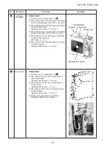
Detail A
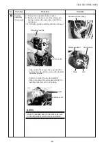
Propeller fan
Propeller fan
Loosened by
Loosened by
turning clockwise
turning clockwise
Flange nut
Flange nut
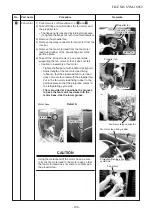
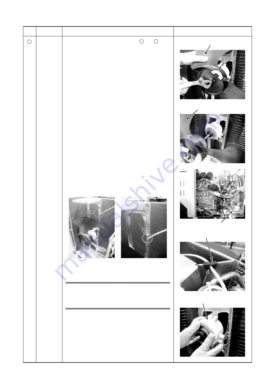
Fan motor
Fan motor
Fan motor
Fan motor relay connector
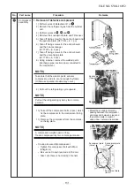
Fan motor lead fixing rubber
Detail A
Detail A
Lower groove
Lower groove
Detail A
Lower groove
Projection/Refrigerating
Projection/Refrigerating
cycle side
cycle side
Loosened by
turning clockwise
Flange nut
Projection/Refrigerating
cycle side
Fan motor
No.
8
Part name
Fan motor
Procedure
1) Perform works of Detachment 1 of
1
and
2
.
2) Take off flange nut which fixes the fan motor and
the propeller fan.
∗
The flange nut is loosened by turning it clockwise.
(To tighten the flange nut, turn it counterclockwise.)
3) Remove the propeller fan.
4) Remove the relay connector for fan motor from the
inverter.
5) Remove the fan motor lead from the fan motor
lead fixing rubber of the penetrating part of the
partition plate.
6) Take off the fixing screws (4 pcs. each) while
supporting the fan motor so that it does not fall.
∗
Caution to assembly of fan motor
• Tighten the flange nut with 4.95N•m (50kgf•cm).
• Adjust length of the fan motor lead fixing
rubber so that the slackened fan motor lead
does not come to contact with the propeller fan.
Put in the fan motor lead fixing rubber to the
partition plate so that the projection comes to
the refrigerating cycle side.
•
There provided at 2 positions the grooves
to pass the fan motor lead wire into the
motor base. Use the lower groove.
CAUTION
Using the metal band of the motor base, be sure
to fix the fan motor lead to the motor base so that
the fan motor lead does not come to contact with
the propeller fan.
Remarks
FILE NO. SVM-18052
- 100 -


