– 73 –
10-6. Grounding
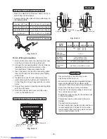
This air conditioner must be grounded without fail.
Grounding is necessary not only to safeguard
against the possibility of receiving an electric shock
but also to absorb both the static, which is generated
by high frequencies and held in the surface of the
outdoor unit, and noise since the air conditioner
incorporates a frequency conversion device
(called an inverter) in the outdoor unit.
If the air conditioner is not grounded, users may
receive an electric shock if they touch the surface of
the outdoor unit and that unit is charged with static.
10-7. Check and Test Operation
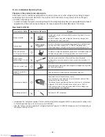
For R410A, use the leak detector exclusively
manufactured for HFC refrigerant
(R410A, R134a, etc.)
∗
The conventional leak detector for HCFC
refrigerant (R22, etc.) cannot be used because its
sensitivity for HFC refrigerant lowers to approx. 1/
40 of that manufactured exclusively for HFC
refrigerant.
• Pressure of R410A becomes approx. 1.6 times
that of R22. If installation work has not completely
finished, gas leaks may occur in cases such as
when pressure rises during operation.
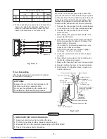
• Check the flare nut connections, valve stem cap
connections and service port cap connections for
gas leaks with a leak detector or soap water.
CAUTION
• Use a circuit breaker of a type that is not
tripped by shock waves.
• Incorrect/incomplete wiring will cause electri-
cal fires or smoke.
• Prepare the power source for exclusive use
with the air conditioner.
• Proceed as follows when connecting the
product to the mains power.
• Connection to fixed wiring:
A switch or circuit breaker which discon-
nects all poles and has a contact separa-
tion of at least 3 mm must be incorporated
into the fixed wiring.
Utilize only approved short circuit breakers
and switches.
∗
(A breaker having sensitivity of approxi-
mately 0.1 second or less and capacity
of approximately 30 mA is usually used.)
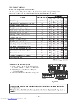
10-7-1. Miswiring (Mis-piping) Check
Make sure that the wiring and piping for each room
have the same alphabetical code (A, B).
Connect and secure the power cord.
Use the power cord/cables with thickness, type, and
protective devices specified in this manual.
Insulate the unused cords (conductors) with PVC
tape.
1. Turn on the electrical power breaker.
2. Operate the indoor unit in cooling mode.
3. Start checks.
• Run the indoor unit in room A, and confirm cool
air blows out.
• Confirm the indoor unit in room B is not run-
ning. (Also check at this time that refrigerant,
which can be heard, is not flowing.)
• Stop operation of the indoor unit in room A and
execute the same checks on the indoor unit in
room B.
Fig. 10-7-1
Flare nut connections
(Indoor unit)
Flare nut connections (Outdoor unit)
Valve stem cap connection
Service port cap connection

