background image

Installation Manual

– 2 –

EN

• THIS AIR CONDITIONER USES THE NEW HFC REFRIGERANT 

(R410A), WHICH DOES NOT DESTROY THE OZONE LAYER. 

R410A refrigerant is apt to be affected by impurities such as water, 
oxidizing membranes, and oils because the pressure of R410A 
refrigerant is approx. 1.6 times of refrigerant R22. As well as the 
adoption of this new refrigerant, refrigerating machine oil has also 
been changed. Therefore, during installation work, be sure that 
water, dust, former refrigerant, or refrigerating machine oil does not 
enter the refrigeration cycle of a new-refrigerant air conditioner. 
To avoid mixing refrigerant and refrigerating machine oil, the sizes 
of charging port connecting sections on the main unit are different 
from those for the conventional refrigerant, and different size tools 
are also required. For connecting pipes, use new and clean piping 
materials with high pressure withstand capabilities, designed for 
R410A only, and ensure that water or dust does not enter. 
Moreover, do not use any existing piping as its pressure withstand 
may be insufficient and may contain impurities.

DANGER

• FOR INSTALLATION BY QUALIFIED PERSONS ONLY.
• MEANS FOR DISCONNECTION FROM THE SUPPLY HAVING A 

CONTACT SEPERATION OF AT LEAST 3 mm IN ALL POLES 
MUST BE INCORPORATED IN THE FIXED WIRING.

• TURN OFF MAIN POWER SUPPLY BEFORE ATTEMPTING ANY 

ELECTRICAL WORK. MAKE SURE ALL POWER SWITCHES 
ARE OFF. FAILURE TO DO SO MAY CAUSE ELECTRIC SHOCK.

• CONNECT THE CONNECTING CABLE CORRECTLY. IF THE 

CONNECTING CABLE IS CONNECTED WRONGLY, ELECTRIC 
PARTS MAY BE DAMAGED.

• CHECK THE EARTH WIRE THAT IT IS NOT BROKEN OR 

DISCONNECTED BEFORE INSTALLATION.

• DO NOT INSTALL NEAR CONCENTRATIONS OF 

COMBUSTIBLE GAS OR GAS VAPORS. FAILURE TO FOLLOW 

THIS INSTRUCTION CAN RESULT IN FIRE OR EXPLOSION.

• TO PREVENT OVERHEATING THE INDOOR UNIT AND 

CAUSING A FIRE HAZARD, PLACE THE UNIT WELL AWAY 
(MORE THAN 2 M) FROM HEAT SOURCES SUCH AS 
RADIATORS, HEATERS, FURNACE, STOVES, ETC.

• WHEN MOVING THE AIR CONDITIONER FOR INSTALLING IT IN 

ANOTHER PLACE AGAIN, BE VERY CAREFUL NOT TO GET 
THE SPECIFIED REFRIGERANT (R410A) WITH ANY OTHER 
GASEOUS BODY INTO THE REFRIGERATION CYCLE. IF AIR 
OR ANY OTHER GAS IS MIXED IN THE REFRIGERANT, THE 
GAS PRESSURE IN THE REFRIGERATION CYCLE BECOMES 
ABNORMALLY HIGH AND IT RESULTINGLY CAUSES BURST 
OF THE PIPE AND INJURIES ON PERSONS.

• IN THE EVENT THAT THE REFRIGERANT GAS LEAKS OUT OF 

THE PIPE DURING THE INSTALLATION WORK, IMMEDIATELY 
LET FRESH AIR INTO THE ROOM. IF THE REFRIGERANT GAS 
IS HEATED BY FIRE OR SOMETHING ELSE, IT CAUSES 
GENERATION OF POISONOUS GAS.

• WHEN INSTALLING OR RE-INSTALLING THE AIR 

CONDITIONER, DO NOT INJECT AIR OR OTHER SUBSTANCES 
BESIDES THE DESIGNATED REFRIGERANT “R410A” INTO THE 
REFRIGERATING CYCLE. IF AIR OR OTHER SUBSTANCES ARE 
MIXED, AN ABNORMAL PRESSURE CAN OCCUR IN THE 
REFRIGERATING CYCLE, AND THIS CAN CAUSE AN INJURY 
DUE TO A PIPE RUPTURE.

WARNING

• Installation work must be requested from the supplying retail 

dealership or professional vendors. Self-installation may cause water 
leakage, electrical shock, or fire as a result of improper installation.

• Specified tools and pipe parts for model R410A are required, and 

installation work must be done in accordance with the manual. 
HFC type refrigerant R410A has 1.6 times more pressure than that 

EN-3

EN-4

Summary of Contents for RAS-M07G3DV Series

Page 1: ...esky Русский Hrvatski Magyar Nederlands Svenska Suomi Norsk Dansk Română Български Eesti Latviski Slovenčina Slovenščina AIR CONDITIONER MULTI SPLIT TYPE Installation Manual Indoor Unit Model name Concealed Duct Type RAS M07G3DV Series RAS M10G3DV Series RAS M13G3DV Series RAS M16G3DV Series ...

Page 2: ...n a high possibility of severe injury 1 or death WARNING It indicates that incorrect use of this unit may cause severe injury or death CAUTION It indicates that incorrect use of this unit may cause personal injury 2 or property damage 3 1 A severe injury refers to blindness injury burns hot or cold electrical shock bone fracture or poisoning that leaves aftereffects and requires hospitalization or...

Page 3: ...MAY BE DAMAGED CHECK THE EARTH WIRE THAT IT IS NOT BROKEN OR DISCONNECTED BEFORE INSTALLATION DO NOT INSTALL NEAR CONCENTRATIONS OF COMBUSTIBLE GAS OR GAS VAPORS FAILURE TO FOLLOW THIS INSTRUCTION CAN RESULT IN FIRE OR EXPLOSION TO PREVENT OVERHEATING THE INDOOR UNIT AND CAUSING A FIRE HAZARD PLACE THE UNIT WELL AWAY MORE THAN 2 M FROM HEAT SOURCES SUCH AS RADIATORS HEATERS FURNACE STOVES ETC WHEN...

Page 4: ... earth work may be the cause of electrical shock Do not install the unit where flammable gas may leak If there is any gas leakage or accumulation around the unit it can cause a fire Do not select a location for installation where there may be excessive water or humidity such as a bathroom Deterioration of insulation may cause electrical shock or fire Installation work must be performed following t...

Page 5: ... running CAUTION Exposure of unit to water or other moisture before installation could result in electric shock Do not store it in a wet basement or expose to rain or water After unpacking the unit examine it carefully for possible damage Do not install in a place that can increase the vibration of the unit Do not install in a place that can amplify the noise level of the unit or where noise and d...

Page 6: ...ked filters may cause the air conditioner s performance to deteriorate condensation to form the plastic parts to be damaged and other such problems to result Places where iron or other metal dust is present If iron or other metal dust adheres to or collects on the interior of the air conditioner it may spontaneously combust and start a fire Locations near obstructions such as ventilation openings ...

Page 7: ...h come to contact with the high humidity atmosphere Apply also a sufficient heat insulation to the duct and connecting part of the duct Installation space Reference Condensation test conditions Indoor side 27 C dry bulb temperature 24 C wet bulb temperature Air volume Low air volume operation time 4 hours A 235 or more Air outlet Refrigerant piping 5 or more Drain piping 210 450 Ceiling 100 100or ...

Page 8: ...on make sure not to make mistake to install the setting direction Carry the package by two or more persons and do not bundle it with plastic band at positions other than specified To install vibration isolation material to hanging bolts confirm that it does not increase the unit vibration External dimensions Hanging bolt Model type A B C M07 10 13G3DV 770 700 650 M16G3DV 970 900 850 Hanging bolt p...

Page 9: ... washers at up and down of the hanging bracket of the indoor unit to hang down the indoor unit Check that four sides are horizontal with a level gauge Horizontal degree Within 5 mm REQUIREMENT Hang the unit in a horizontal position When unit is hanged to slant it may cause overflow of drainage Install the unit within the dimension according to the figure below Use level gauge to confirm whether th...

Page 10: ... does not fit in the wall cut spacers to adjust the clearance 8 m o r l e s s Signal receiving unit Switch box Locally procured Spacer Screw M4 x 25 mm Lower case Signal receiving unit Fig 1 3 Connect the housing of Signal receiving unit with the connector of wires extended from the indoor unit Fig 2 4 Reattach the upper case Mounting on the ceiling 1 Cut a section out of the ceiling along the pro...

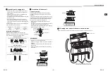
Page 11: ...e connecting port Hard socket Attached hose band Adhesive inhibited Use the attached flexible hose and hose band for connecting the drain hose to the clear drain socket If applying the adhesive socket will be damaged and cause water leakage Indoor unit Soft socket Hard socket Socket for VP25 Locally procured Attached flexible hose VP25 vinyl chloride pipe Locally procured 15 mm or less 10 to 12 mm...

Page 12: ...Do not apply a 220 V to 240 V voltage to A B of the terminal block Otherwise the printed circuit board may be damaged Pour the water by following the method shown in the following figure Amount of water poured 1500 cc to 2000 cc When the power is turned on the drain pump automatically starts running Check whether the water is draining from the drain pipe connecting port and check that no water is ...

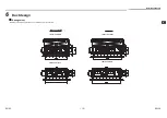
Page 13: ...n Manual 12 EN 6 Duct design Arrangement Referring to the following dimensions manufacture duct at the local site M07 10 13G3DV M16G3DV Under air intake Under air intake Back air intake Back air intake EN 23 EN 24 ...

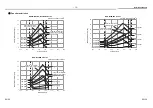
Page 14: ... Low 45Pa Low 35Pa Low 20Pa Low 10Pa High 45Pa Lower limit of external static pressure 45Pa High 35Pa High 10Pa High 20Pa Upper limit of external static pressure 45Pa High 45Pa Lower limit of external static pressure 45Pa High 35Pa High 10Pa High 20Pa Low 35Pa Low 20Pa Low 10Pa Low 45Pa 0 10 20 30 40 50 60 200 300 400 500 600 700 800 900 Standard Air Volume 780m3 h RAS M16G3DV Series External Stat...

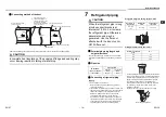
Page 15: ...pe cutter Remove burrs completely Remaining burrs may cause gas leakage 2 Insert a flare nut into the pipe and flare the pipe Use the flare nut provided with the unit or the one used for the R410A refrigerant The flaring dimensions for R410A are different from the ones used for the conventional R22 refrigerant A new flare tool manufactured for use with the R410A refrigerant is recommended but the ...

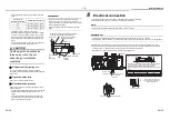
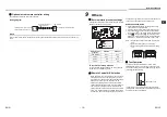
Page 16: ...tached heat insulator without any gap between the indoor unit The seam must be faced upward ceiling side Indoor unit Flare nut Union Heat insulation pipe Accessory Banding band Locally procured Heat insulator of the pipe 8 Electrical connection 1 The supply voltage must be the same as the rated voltage of the air conditioner 2 Prepare the power source for exclusive use with the air conditioner NOT...

Page 17: ...and remote control are different There is no relation between A setting B setting and A room B room when connecting the piping and cables To separate using of remote control for each indoor unit in case of 2 air conditioners are installed near Remote Control B Setup 1 Press TEMPORARY button on the signal receiving unit to turn the air conditioner ON 2 Point the remote control at the signal receivi...

Page 18: ...with Auto Restart function in the off position Turn it on as required How to set the Auto Restart 1 Press and hold the TEMPORARY button on the signal receiving unit for 3 seconds to set the operation 3 beep sound and OPERATION lamp blink 5 time sec for 5 seconds 2 Press and hold the TEMPORARY button on the signal receiving unit for 3 seconds to cancel the operation 3 beep sound but OPERATION lamp ...

Page 19: ...EG55760001 00 ...
Reviews: