background image

– 33 –

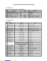
Item

Operation 

fl

 ow and applicable data, etc.

Description

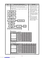
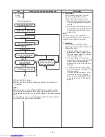
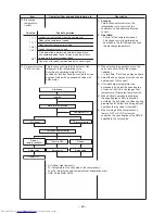
2. Indoor fan 

motor control 
(Continued)

[In starting and in stability]

(Table 2)  Indoor fan air flow rate (Heating)

FAN AUTO

FAN Manual

In starting

• Until 12 minutes passed after operation start
• When 12 to 25 minutes passed after operation start

and room temp. is 3°C or lower than set temp.

• Room temp. < Set temp. –4°C

In stability

• When 12 to 25 minutes passed after operation start

and room temp. is higher than (set temp. –3°C)

• When 25 minutes or more passed after operation start

• Room temp.

r

Set temp. –3.5°C

Fan speed level

WF

WE

UH

WD

H

WC

M+

WB

WA

M

W9

W8

L+

W7

L

W6

L–

W5

UL

W4

W3

SUL

W2

W1

RAS-M10PKVP-E

Fan speed Air flow rate

(rpm)

(m

3

/h)

1140

640

1140

640

1070

590

  980

530

  900

470

  850

430

  810

400

  710

330

  710

330

  650

290

  650

290

  650

290

  650

290

  560

220

  420

120

RAS-M13PKVP-E

Fan speed Air flow rate

(rpm)

(m

3

/h)

1200

690

1200

690

1100

610

1010

550

  930

490

  850

430

  810

400

  710

330

  710

330

  650

290

  650

290

  650

290

  650

290

  560

220

  420

120

RAS-M16PKVP-E

Fan speed Air flow rate

(rpm)

(m

3

/h)

1280

750

1280

750

1180

670

1090

610

  980

530

  900

470

  880

450

  780

380

  710

330

  700

320

  650

290

  650

290

  650

290

  560

220

  420

120

Summary of Contents for RAS-M10PKVP-E

Page 1: ...R410A FILE NO A010 024 PRINTED IN JAPAN Mar 2011 SERVICE MANUAL SPLIT TYPE Heat PumpType t i n U r o o d n I RAS M10PKVP E RAS M13PKVP E RAS M16PKVP E t i n U r o o d t u O RAS M18UAV E AIR CONDITIONER ...

Page 2: ...17 WIRING DIAGRAM 19 SPECIFICATIONS OF ELECTRICAL PARTS 21 REFRIGERANT CYCLE DIAGRAM 22 CONTROL BLOCK DIAGRAM 24 OPERATION DESCRIPTION 26 INSTALLATION PROCEDURE 52 HOW TO DIAGNOSE THE TROUBLE 72 HOW TO REPLACE THE MAIN PARTS 94 EXPLODED VIEWS AND PARTS LIST 110 1 2 3 4 5 6 7 8 9 10 11 12 13 ...

Page 3: ...conventional refrigerant units Accordingly special tools are required for the new refrigerant R410A units For connecting pipes use new and clean piping materials with high pressure fittings made for R410A only so that water and or dust does not enter Moreover do not use the existing piping because there are some problems with pressure fittings and possible impurities in existing piping CAUTION TO ...

Page 4: ...d flows near a fire source such as a cooking range noxious gas may generate The electrical work must be performed by a qualified electrician in accordance with the Installation Manual Make sure the air conditioner uses an exclusive circuit An insufficient circuit capacity or inappropriate installation may cause fire When wiring use the specified cables and connect the terminals securely to prevent...

Page 5: ... RAS M18UAV E 07 07 07 10 07 13 07 16 10 10 10 13 10 16 13 13 13 16 A 1 room connection is not an option for the indoor units you cannot connect only one indoor unit A 2 room connection must always be used for the indoor units you must connect two indoor units With the RAS M18UAV E outdoor unit model the 16 16 combination is not an option NOTES The contents noted in this service manual limit the i...

Page 6: ...750 Outdoor unit Dimension Height mm 550 Width mm 780 Depth mm 290 Net weight kg 41 Compressor Motor output W 1100 Type Twin rotary type with DC inverter variable speed control Model DA130A1F 25F Fan motor output W 43 Air flow rate m h 2300 2400 Type Flare connection Piping connection Indoor unit Unit model RAS M10PKVP E RAS M13PKVP E RAS M16PKVP E Liquid side Gas side Ø6 35 Ø9 52 Ø6 35 Ø9 52 Ø6 3...

Page 7: ... 2 6 19 1 55 to 9 23 1440 260 to 2170 Heating RAS M18UAV E Operation mode Volts V Operation status Operating indoor unit Unit capacity kW Capacity kW Running current A Power Consumption W A B A B Heating 220 1 unit 07 2 7 2 7 0 7 to 4 8 3 65 1 10 to 7 88 730 170 to 1700 10 4 0 4 0 0 7 to 5 2 5 62 1 10 to 7 88 1200 170 to 1700 13 5 0 5 0 0 7 to 6 5 8 43 1 10 to 11 73 1800 170 to 2530 16 5 5 5 5 0 7...

Page 8: ... DB 20 C Outdoor DB 7 C WB 6 C Air flow High Pipe length 7 5m 2 2 units oper 230V 2 2 2 Capacity Variation Ratio According to Temperature RAS M18UAV E Cooling Cooling C p m e t b l u b t e w r i a r o o d n I Capacity ratio 105 110 115 100 95 90 85 0 14 16 18 20 22 24 Conditions Indoor DB 27 C Outdoor DB 35 C Indoor air flow High Pipe length 7 5m 2 2 units operating Capacity ratio 100 5 2 kW C p m...

Page 9: ... pressure in the refrigeration cycle may become abnormally high so that a rupture or personal injury may be caused 5 After completion of installation work check to make sure that there is no refrigeration gas leakage If the refrigerant gas leaks into the room coming into contact with fire in the fan driven heater space heater etc a poisonous gas may occur 6 When an air conditioning system charged ...

Page 10: ...es of socket joints Nominal diameter Reference outer diameter of copper pipe jointed mm Minimum joint thickness mm 1 4 6 35 0 50 3 8 9 52 0 60 1 2 12 70 0 70 5 8 15 88 0 80 3 2 2 Processing of Piping Materials When performing the refrigerant piping installation care should be taken to ensure that water or dust does not enter the pipe interior that no other oil than lubricating oils used in the ins...

Page 11: ... 0 5 1 0 to 1 5 1 5 to 2 0 1 2 12 70 0 8 0 to 0 5 1 0 to 1 5 2 0 to 2 5 5 8 15 88 1 0 0 to 0 5 1 0 to 1 5 2 0 to 2 5 Table 3 2 4 Dimensions related to flare processing for R22 Nominal diameter Outer diameter mm Thickness mm A mm Flare tool for R22 clutch type Conventional flare tool Clutch type Wing nut type 1 4 6 35 0 8 0 to 0 5 0 5 to 1 0 1 0 to 1 5 3 8 9 52 0 8 0 to 0 5 0 5 to 1 0 1 0 to 1 5 1 ...

Page 12: ...ightening torque for R410A is the same as that for conventional R22 Incidentally when the torque is weak the gas leakage may occur When it is strong the flare nut may crack and may be made non removable When choosing the tightening torque comply with values designated by manufacturers Table 3 2 7 shows reference values NOTE When applying oil to the flare surface be sure to use oil designated by th...

Page 13: ...tool Pipe flaring Yes Note 1 2 Copper pipe gauge for adjusting projection margin Flaring by conventional flare tool Yes Note 1 Note 1 3 Torque wrench For Ø12 7 Connection of flare nut Yes 4 Gauge manifold Evacuating refrigerant charge run check etc Yes 5 Charge hose 6 Vacuum pump adapter Vacuum evacuating Yes 7 Electronic balance for refrigerant charging Refrigerant charge Yes 8 Refrigerant cylind...

Page 14: ...nsure that the compound gauge s pointer does not return Set the refrigerant cylinder to the electronic balance connect the connecting hose to the cylinder and the connecting port of the electronic balance and charge liquid refrigerant 1 Never charge refrigerant exceeding the specified amount 2 If the specified amount of refrigerant cannot be charged charge refrigerant bit by bit in COOL mode 3 Do ...

Page 15: ... filler is an alloy mainly composed of silver and copper It is used to join iron copper or copper alloy and is relatively expensive though it excels in solderability 2 Phosphor bronze brazing filler Phosphor bronze brazing filler is generally used to join copper or copper alloy 3 Low temperature brazing filler Low temperature brazing filler is generally called solder and is an alloy of tin and lea...

Page 16: ... pipe the lubricating oil deteriorates Therefore use a flux which does not contain chlorine 3 When adding water to the flux use water which does not contain chlorine e g distilled water or ion exchange water 4 Remove the flux after brazing 3 5 3 Brazing As brazing work requires sophisticated techniques experiences based upon a theoretical knowledge it must be performed by a person qualified In ord...

Page 17: ...0 or more Drain hose detail dia 28 dia 16 dia 14 Inner diameter Outer diameter Heat insulation 19 19 Wireless remote controller 163 58 Remote controller holder 4 5 74 5 64 34 dia 4 2 125 5 Refrigerant pipe connecting port Liquid side Flare dia 6 35 Outside length 0 4m Refrigerant pipe connecting port Gas side Flare dia 9 52 16PKVP E dia 12 7 Outside length 0 35m Drain hose VP16 Outside length 0 54...

Page 18: ... 18 4 2 Outdoor Unit RAS M18UAV E Heat pump models ...

Page 19: ...N21 WHI CN401 RED CN604 RED CN212 CN301 WHI CN261 WHI BLK BLK 10 12 14 16 18 8 9 8 7 6 5 4 3 2 1 10 10 0 10 0 11 12 13 14 15 16 17 7 18 8 19 9 21 2 22 22 23 23 24 24 9 8 7 6 5 4 3 2 1 5 5 1 1 TCj BLK BLK 1 Thermo sensor TA BLK BLK Humidity sensor BLK WHI WHI RED WHI BLU BLU BLU WHI YEL YEL WHI YEL RED WHI RED BLK 1 3 4 6 1 2 1 3 2 1 5 4 3 2 1 5 4 CN221 WHI 10 0 10 0 3 2 1 5 1 1 2 4 3 2 1 Varistor ...

Page 20: ... 20 5 2 Outdoor Unit RAS M18UAV E Heat pump models ...

Page 21: ...A AC250V 5 Relay Power relay G4A 1A PE Coil DC 12V Contact 20A AC250V 6 Discharge temp sensor TD sensor Inverter attached 1 905kΩ 120 C 7 Outside air temp sensor TO sensor Inverter attached 10kΩ 25 C 8 TGa sensor Heat pump models Inverter attached 10kΩ 25 C 9 TGb sensor Heat pump models Inverter attached 10kΩ 25 C 10 Evaporator temp sensor TE sensor Inverter attached 10kΩ 25 C 11 Suction temp sens...

Page 22: ... B room Outer dia 6 35mm Thickness 0 8mm Sectional shape of heat insulator Allowable height difference 10m Allowable pipe length P Pressure measurement Gauge attaching port Vacuum pump connecting port Strainer Pulse motor valve at liquid side CAM B22YGTF 3 TD TGa TGb 4 way valve STF 0213Z Compressor DA130A1F 25F TS T2 Outdoor heat exchanger Temp measurement Propeller fan Refrigerant amount 1 20kg ...

Page 23: ...9 to 1 1 13 to 15 44 to 46 High 850rpm 71 Heating RAS M18UAV E Temperature condition C No of operating units Operating combination unit Standard pressure Heat exchanger pipe temp Indoor fan Outdoor fan Compresser revolution rps Indoor Outdoor A B P MPa T1 C T2 C 20 7 6 1 unit 07 2 4 to 2 6 37 to 39 2 to 4 High 750rpm 44 10 2 6 to 2 8 45 to 46 2 to 4 High 900rpm 62 13 3 0 to 3 2 51 to 53 2 to 4 Hig...

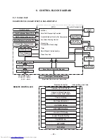
Page 24: ...er Supply Circuit Converter D C circuit Infrared Rays 36 7kHz Remote Controller Operation START STOP Thermo Setting Fan Speed Selection ON TIMER Setting OFF TIMER Setting Louver AUTO Swing Louver Direction Setting Hi POWER Operation Mode Selection AUTO COOL DRY HEAT REMOTE CONTROLLER SLEEP Mode Air Purifier Heat Exchanger Sensor Tc Heat Exchanger Sensor Tcj Humidity sensor Room Temperature Sensor ...

Page 25: ... M Current detect Current detect M C U Inverter output frequency control A D converter function P M V control Discharge temp control Error displey Signal communication to MCU M C PWM synthesis function Input current release control IGBT over current detect control Outdoor fan control High power factor correction control Signal communication to MCU Gas side pipe temp sensor unit B TGb Gas side pipe...

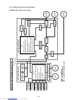
Page 26: ... unit controller Receiving the operation command signal Serial signal from the indoor unit controller the outdoor unit performs its role Compressor operation control Operation control of outdoor fan motor P M V control 4 way valve control Operations followed to judgment of serial signal from indoor side Operations followed to judgment of serial signal from indoor side Detection of inverter input c...

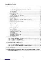
Page 27: ...sition 38 2 Air direction adjustment 38 3 Swing 38 10 SLEEP MODE operation 39 11 Temporary operation 40 12 Air purifying control 40 13 Discharge temperature control 42 14 Pulse motor valve P M V control 42 15 Clean operation 43 16 Clean operation cancel 44 17 Select switch on remote controller 45 18 Set temperature correction 46 9 3 Auto Restart Function 47 9 3 1 Setting the Auto Restart Function ...

Page 28: ... OFF Air conditioner Air purifier Operation select COOL HEAT AUTO DRY Temperature setup Air direction Swing Air volume select AUTO LOW LOW MED MED HIGH Sleep mode ON timer setup OFF timer setup High power Indoor unit control Command signal generating function of indoor unit operation Calculation function temperature calculation Activation compensation function of indoor fan Cold draft preventive f...

Page 29: ...on Cleaning operation Heating Heating Cleaning operation Actual indoor unit operation Cooling dry Cooling dry Heating Heating Fan solo air purification Fan solo air purification Fan solo air purification Cooling dry Cooling dry Fan solo air purification Cooling dry Fan stopped Heating Fan stopped Fan solo air purification Fan stopped Heating Fan stopped Cleaning operation Cleaning operation Cleani...

Page 30: ...omatically the status of room temperature Ta when starting AUTO operation Ts 1 Ts 1 Ta Cooling operation Monitoring Fan Heating operation Heat pump model 1 When reselecting the operation mode the fan speed is controlled by the previous operation mode 5 DRY operation 1 Detects the room temperature Ta when the DRY operation started 2 Starts operation under conditions in the left figure according to ...

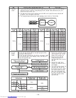
Page 31: ...he setup temperature room temperature and heat exchanger temperature 4 When the fan speed mode is AUTO and the compressor stops the fan speed is controlled from W2 20 seconds to 0 rpm 40 seconds 2 5 Ta C 2 0 1 5 1 0 0 5 Tsc a b c d e M WC 3 4 5 L W7 Fan speed H WD 6 7 8 L W8 Hi Power L L M M H W8 L M 2 WC M H 2 WE Indication Hi Power W7 L M 2 WA M H 2 WD Fan speed Fan speed setup COOL ON AUTO MANU...

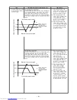
Page 32: ...d 1 5 e 2 0 f 2 5 g 5 0 5 5 L W9 4 1 2 3 M WD Hi Power M WB 8 5 6 7 H WE H WE Line approximate H and SUL with Tc SUL W2 Stop 46 46 Tc 34 45 45 33 33 33 21 32 32 20 A 4 A 4 A 4 A 4 A 4 A 4 Fan speed MANUAL in starting Fan speed AUTO in stability Fan speed AUTO in starting L L M M H W8 L M 2 WB M H 2 WE Indication Fan speed W9 L M 2 WD M H 2 WF Hi Power YES NO Min air flow rate control MANUAL Tc 52 ...

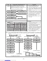
Page 33: ...en 25 minutes or more passed after operation start Room temp r Set temp 3 5 C Fan speed level WF WE UH WD H WC M WB WA M W9 W8 L W7 L W6 L W5 UL W4 W3 SUL W2 W1 RAS M10PKVP E Fan speed Air flow rate rpm m3 h 1140 640 1140 640 1070 590 980 530 900 470 850 430 810 400 710 330 710 330 650 290 650 290 650 290 650 290 560 220 420 120 RAS M13PKVP E Fan speed Air flow rate rpm m3 h 1200 690 1200 690 1100...

Page 34: ... selected 2 Fan speed 400 when the motor stopped Air conditioner ON Remote controller YES YES NO NO Indoor unit controller Fan motor ON 3 Fan lock OFF status of fan motor continues 4 Motor operates as shown in the table below 1 Outdoor unit operation command Outdoor fan control Air conditioner OFF Alarm display Cooling operation dry operation RAS M18UAV E Compressor revolution rps TO 38 C 28 TO b ...

Page 35: ...6 07 10 10 13 13 16 16 13 16 15 to 120 15 to 83 07 10 13 16 07 10 10 13 13 16 16 13 16 07 07 10 07 10 07 10 13 13 07 07 10 07 10 07 10 13 13 5 Current release control This function prevents troubles on the electronic parts of the compressor driving inverter This function also controls drive circuit of the compressor speed so that electric power of the compressor drive circuit does not exceed the s...

Page 36: ...or heat exchanger temperature When the value is in Q zone the compressor speed is kept In heating operation Prevent overpressure control for refrigerating cycle In heating operation the sensor of indoor heat exchanger detects condensation temperature and controls the compressor speed so that temperature of the heat exchanger does not exceed the specified value 1 When temperature of the indoor heat...

Page 37: ... fan stops at the same time when the compressor stops 4 When temperature of the indoor heat exchanger becomes 38 C or lower stop the indoor fan Finish of defrost operation Returning conditions from defrost operation to heating operation 1 Temperature of outdoor heat exchanger rises to 8 C or higher 2 Temperature of outdoor heat exchanger is kept at 5 C or higher for 80 seconds 3 Defrost operation ...

Page 38: ...ring 12 minutes or 12 to 25 minutes from start of heating operation Room temperature TA Set temperature Tsc 3 0 In case that the following temperature is obtained during 12 to 25 minutes from start of heating operation Room temperature TA r Set temperature Tsc 3 0 or when 25 minutes or more passed from start of heating operation Heating storage position Louver Directs downward 72 Cooling storage p...

Page 39: ...n in the left figure 2 The set temperature increased 0 5 C per hour up to 2 C starting from the set temperature when SLEEP MODE has been received 1H 2H 3H 4H time W6 Fan speed Time correction W5 W4 W3 1 zone 0 1 zone min 1 TA Tsc C 4 0 3 5 3 0 2 5 2 0 1 5 1 0 0 5 0 0 1 0 6 5 6 0 5 5 5 0 4 5 0 5 1 5 2 0 Heating operation 1 The indoor fan speed is controlled within W7 as maximum value 2 The louver p...

Page 40: ... starts operation and if it is received while the air conditioner operates the air conditioner and the air purifier start operation The air ion generator operates linked with the air purifying operation Present status Stop Air purifier only Air conditioner Joint use of AC and air purifier Operation button PURE button Air conditioner Air purifier AC operation Stop All AC Air purifier AC Air purifie...

Page 41: ...s up determine the error and turn on the PURE indicator Orange 3 The FILTER indicator keeps lighting even if the operation is stopped by the remote controller The timer is stored in memory of the microcomputer and the operation time is cleared by filter RESET button on the indoor unit FILTER indicator goes off Air purifying operation Operation indicator ON PURE indicator Blue ON Air purifier ON Er...

Page 42: ...unction also controls the open degree of valve with an expansion valve with pulse motor 1 When starting the operation move the valve once until it fits to the stopper Initialize In this time Click sound may be heard 2 Adjust the open degree of valve by super heat amount SH control 3 If the discharge temperature was excessively up adjust the open degree of valve so that it is in the range of set te...

Page 43: ... period of the clean operation is determined by the duration of the operation performed prior to the reception of the stop code 3 After the clean operation has been performed for the specified period the unit stops operating Unit now performing cooling or dry operation Push STOP button Only S CLEAN indicator lights and clean operation starts Time set now elapses Operation stops During clean operat...

Page 44: ... indoor unit for at least 3 seconds but not more than 10 seconds The indoor unit s buzzer emits three beeps and the OPERATION indicator flashes at 5 Hz intervals This completes the clean operation setting Indoor P C board CAUTION J231 will be near the MCU so take steps to ensure that it will not be exposed to excessive levels of heat Also take care to avoid solder bridging with the surrounding com...

Page 45: ...mper wire inside the battery box using pliers 1 Slide open the remote controller cover and remove the batteries 2 Cut the jumper wire inside the battery compartment using nippers The jumper wire should not remain in contact after being cut Also be careful not to let plastic scraps jumper wire cuttings or other debris enter the inside of the remote controller 3 Insert the batteries B appears in the...

Page 46: ...ifference between the set temp of the remote controller and the room temp is wide due to the installation condition etc the set temp is corrected HEAT operation only 2 Description The set temp received from the remote controller is corrected The correct value from 2 C to 4 C is changed by the jumper wire on P C board of the indoor microcomputer k At shipment With Jumper wire Cut Jumper wire Jumper...

Page 47: ...ESET button for more than 3 seconds Less than 10 seconds The unit is on standby Push RESET button for more than 3 seconds The unit starts to operate The green indicator is on After approx 3 seconds The unit beeps 3 times and continues to operate The green indicator flashes for 5 seconds If the unit is not required to operate at this time push RESET button once more or use the remote controller to ...

Page 48: ...is time push RESET button once more or use the remote controller to turn it off When the system is operating Operation Motions Push RESET button for more than 3 seconds Less than 10 seconds The unit is in operation The green indicator is on Push RESET button for more than 3 seconds The unit stops operating The green indicator is turned off After approx 3 seconds The unit beeps 3 times If the unit ...

Page 49: ...N timer button ON Use this button to change the clock and ON timer times To move up the time push of the ON ON button To move down the time push of the ON ON button 9 OFF timer button OFF Use this button to change the OFF timer times To move up the time push of the OFF OFF button To move down the time push of the OFF OFF button 10 Reserve button SET Push this button to store the time settings A re...

Page 50: ...ation 7 Hi POWER indicator Indicates when the Hi POWER operation starts Push the Hi POWER button to start and push it again to stop the operation 8 MEMORY indicator Flashes for 3 seconds when the MEMO button is pressed during operation The mark is shown when holding down the button for 3 seconds or more while the mark is flashing Push another button to turn off the mark 9 SLEEP mode indicator Indi...

Page 51: ...ff occurred the following operations start Refer to the figure below 1 The indoor unit of the room A room in which thermo off did not occur starts a continuous operation with the setup number of revolution 2 The indoor unit of the room B room in which thermo off occurred starts intermittent operation of the indoor fan The indoor fan operates with number of revolution of UL or SUL Fan ON time is 2 ...

Page 52: ...ht Rear left Bottom left Left 8 mm thick heat resisting polyethylene foam The indoor unit shall be installed so that the top of the indoor unit is positioned at least 2 m high Also avoid putting anything on the top of the indoor unit Hook Hook Hook Hook 70 mm or more 160 mm or more 180 mm or more 1 Installation plate 5 Mounting screw 2 Wireless remote controller 2 Wireless remote controller 4 Remo...

Page 53: ...0 2 2 Accessory and Installation Parts Part No Part name Q ty Part No Part name Q ty Part No Part name Q ty 1 Installation plate 1 4 Remote controller holder 1 7 Drain nipple 1 2 Wireless remote controller 1 5 Mounting screw Ø4 25L 7 8 Water proof rubber cap 2 3 Battery 2 6 Remote controller holder mounting screw Ø3 1 16L 2 Parts marked with asterisk are packaged with the outdoor unit Others Name ...

Page 54: ... sides of flare nuts have been increased Incidentally a common wrench is used for nominal diameters 1 4 and 3 8 Flare tool clutch type By increasing the clamp bar s receiving hole strength of spring in the tool has been improved Gauge for projection adjustment Used when flare is made by using conventional flare tool Vacuum pump adapter Connected to conventional vacuum pump It is necessary to use a...

Page 55: ...op view Side view Remote controller Remote controller Indoor unit Axial distance Reception range Reception range 10 3 2 Drilling and Mounting Installation Plate Drilling When installing the refrigerant pipes from the rear Fig 10 3 2 Pipe hole Dia 80 mm 100 mm 45 mm m 1 m from unit edge 100 mm to pipe hole enter 1 Decide the installation plate mounting position on the wall 2 Mark the corresponding ...

Page 56: ...g 10 3 5 Anchor bolt NO GOOD OK NO GOOD Projection 15mm or less 5 mm dia hole Clip anchor local parts 5 Mounting screw Ø4 25L Failure to securely install the unit may result in personal injury and or property damage if the unit falls CAUTION In case of block brick concrete or similar type walls drill 5 mm dia holes in the wall Insert clip anchors for the 5 mounting screws NOTE Install the installa...

Page 57: ...ightly with screws Make a loop with the earth wire under the terminal block and secure it with the earth screw 6 Tightening torque 1 2 N m 0 12 kgf m 7 Secure the connecting cable with the cord clamp 8 Attach the terminal cover and moving panel on the indoor unit Be sure to refer to the wiring system diagram labelled inside the front panel Check local electrical regulations for any specific wiring...

Page 58: ...ace by a screw Remove the screw securing the drain hose then pull out the drain hose Screw Drain hose Fig 10 3 12 4 Attach the drain cap Insert hexagonal wrench 4 mm 4 mm Fig 10 3 13 5 Firmly insert drain cap No gap Insert a hexagon wrench Ø4mm Do not apply lubricating oil refrigerant machine oil when inserting the drain cap If applied deterioration and drain leakage of the drain plug may occur Fi...

Page 59: ...ess Dia 12 7 Make sure to use a spring bender to avoid crushing the pipe Liquid side NOTE If the pipe is incorrectly bent the indoor unit may be unstable on the wall After passing the connecting pipe through the pipe hole connect the connecting pipe to the auxiliary pipes and wrap the facing tape around them Bind the auxiliary pipes two and connecting cable with facing tape tightly In case of left...

Page 60: ...0 3 7 Drainage 1 Run the drain hose at a downward sloped angle NOTE Hole should be made at a slight downward slant on the outdoor side Fig 10 3 21 50 mm or more Do not rise the drain hose Do not form the drain hose into the waved shape Do not put the drain hose end into water Do not put the drain hose end in the drainage ditch OK NO GOOD 2 Put water in the drain pan and make sure that the water is...

Page 61: ...ted Heat pump RAS M18UAV E 07 07 07 10 07 13 07 16 10 10 10 13 10 16 13 13 13 16 NOTE A 1 room connection is not an option for the indoor units you cannot connect only one indoor unit A 2 room connection must always be used for the indoor units you must connect two indoor units With the RAS M18UAV E outdoor unit model the 16 16 combination is not an option ...

Page 62: ...wiring and piping lengths on the inside rather than the outside A place where the drain water does not cause any problems Install the outdoor unit in a location where there are no obstructions near its air intake or air outlet When the outdoor unit is installed in a place that is always exposed to strong winds like on the coast or on a high story of a building secure the normal fan operation using...

Page 63: ...now protection plate Snow protection hood At least 500 mm Snow accumulation line Holding frame Anchor bolts Front Fig 10 5 3 Fixing the outdoor unit Secure the outdoor unit with the anchor bolts Use 8 mm or 10 mm anchor bolts and nuts Set the out margin of the anchor bolt to 15 mm or less Install the outdoor unit so that it is level Install the foundation and vibration proof rubber pads to directl...

Page 64: ... 14 to 18 1 4 to 1 8 9 52 0 8 0 to 0 5 1 5 to 2 0 13 2 22 33 to 42 3 3 to 4 2 12 7 0 8 0 to 0 5 2 0 to 2 5 16 6 26 50 to 62 5 0 to 6 2 Pipe connection 1 Ensure that the same wires and pipes are used for connecting all the indoor and outdoor units 2 Align the centers of the connecting pipes and tighten the flare nut as much as possible with your fingers Then tighten the nut with a wrench and torque...

Page 65: ... infiltrating from an area where a pipe is connected or other place Check the areas where the pipes are connected 3 Close Handle Lo completely Turn OFF the vacuum pump Leave the vacuum pump as it is for 1 or 2 minutes and check that the indicator of the compound pressure gauge does not return No more refrigerant needs to be added if the total pipe length is no more than 20 meters Add 20 g of refri...

Page 66: ...otential GWP of gas 1975 1 Paste the enclose refrigerant label adjacent to the charging and or recovering location 2 Clearly write the charge refrigerant quantity on the refrigerant label using indelible ink 3 Prevent emission of the contained fluorinated greenhouse gas Ensure that the fluorinated greenhouse gas is never vented the atmosphere during installation service or disposal When any leakag...

Page 67: ... a pump down operation be sure to take the following steps Ensure that no air is allowed to enter inside the refrigeration cycle After having closed the two service valves shut down the compressor and then remove the refrigerant pipe If removing the refrigerant pipe while the compressor is operating with the service valve opened it may cause air suction and overpressure inside the refrigeration cy...

Page 68: ...tach the service valve cover on the outdoor unit Stripping length of connecting cable for outdoor unit 30 30 10 L N 10 1 2 3 10 10 40 40 Earth line Connecting cable Power cord Earth line Fig 10 5 15 1 2 3 1 2 3 L N Terminal block Power cord Connecting cable for unit A Connecting cable for unit B Fig 10 5 16 10 5 4 Grounding This air conditioner must be grounded without fail Grounding is necessary ...

Page 69: ...ting must each be performed for at least 10 minutes The cooling and heating operations can be performed using the room temperature sensors of the indoor units Cooling operation Expose the room temperature sensor to a hair dryer or other heating device Heating operation Hold a chilled towel or other article up against the room temperature sensor What is to be explained to the customers While referr...

Page 70: ...m or adjoining rooms when the user tries to operate only one unit both units may receive the same remote controller signal and operate This can be prevented by changing one of the indoor units and remote controllers to setting B the default setting for both units is A If the indoor unit and remote controller settings are different the remote controller signal is not accepted Setting the remote con...

Page 71: ...Trouble on compressor system 1C Gas side pipe temp sensor a TGa fault 1C Gas side pipe temp sensor b TGb fault 1C TGa TGb sensor out of place P M V fault 1C Communication trouble between M C U 1C Compressor lock 1D Trouble on discharge temp Gas leakage 1E Compressor break down 1F LED ON LED OFF These LEDs do not normally light 1 If trouble occurs LED Red goes on according to the contents of troubl...

Page 72: ... Trouble by Every Symptom 79 6 Check Code 1C and 1E 84 No Troubleshooting Procedure Page 7 Trouble Diagnosis by Outdoor LED 85 8 Troubleshooting 86 9 How to Diagnose Trouble in Outdoor Unit 87 10 Inspection of the Main Parts 88 11 How to Simply Judge Whether Outdoor Fan Motor is Good or Bad 93 Precautions when handling the inverter The high voltage circuit is incorporated Be careful to do the chec...

Page 73: ...age to the components CAUTION Sensor leads Do NOT lay the circuit board assembly flat Fig 11 2 Precautions when inspecting the control section of the outdoor unit NOTE A large capacity electrolytic capacitor is used in the outdoor unit controller inverter Therefore if the power supply is turned off charge charging voltage DC280 to 380V remains and discharging takes a lot of time After turning off ...

Page 74: ...s timer operates 3 In DRY and SLEEP MODE FAN air flow display does not change even though FAN air flow select button is operated The air flow indication is fixed to AUTO 4 Increasing of compressor motor speed stops approx 30 seconds after operation started and then compressor motor speed increases again approx 30 seconds after For smooth operation of the compressor the compressor motor speed is re...

Page 75: ...1 3 1 Item Check code Block display Description for self diagnosis Indoor indication lamp flashes Which lamp does flash A OPERATION Green Flashing display 1 Hz Power failure when power is ON B OPERATION Green Flashing display 5 Hz Protective circuit operation for indoor P C board C OPERATION Green TIMER Orange Flashing display 5 Hz Protective circuit operation for connecting cable and serial signa...

Page 76: ... remote controller to the service mode is indicated on the display of the remote controller 2 Push ON or OFF button If there is no fault with a code the indoor unit will beep once Beep and the display of the remote controller will change as follows The TIMER indicator of the indoor unit flashes continuously 5 times per 1 sec Check the unit with all 52 check codes to as shown in Table 11 4 1 Press ...

Page 77: ... board Being out of place disconnection short circuit or migration of heat exchanger sensor TCj sensor Operation continues Displayed when error is detected 1 Check heat exchanger sensor 2 When heat exchanger sensor is normal check P C board Lock of indoor fan or trouble on the indoor fan circuit All off Displayed when error is detected 1 Check the motor 2 When the motor is normal check P C board N...

Page 78: ... on outdoor P C board All off Displayed when error is detected Check 5 serial LED When 20 seconds passed after start up position detect circuit error occurred Replace compressor Trouble on P M V Check gas side temp sensor TG Check P C board Check communication wire between outdoor P C board Check outdoor P C board Others including compressor Return serial signal has been sent when operation starte...

Page 79: ...n motor connector between CN301 1 3 short circuit Item by symptoms Operation Check Item Considerable principle cause Measures Parts R01 R02 DB01 C01 C03 IC01 and T101 are defective Remote controller is defective Refer to 5 Troubleshooting for remote controller Parts of a power supply circuit defective Unit operates normally Replace main P C board Replace fan motor Is fuse F01 of indoor control boa...

Page 80: ...t DC 1V or more between 5 and 3 of motor connector CN301 Start to operate the indoor unit in except heating operation At this time is it possible to detect DC 1V or more between 5 and 3 of motor connector CN301 Check this condition within 15 seconds after starting unit Start to operate the indoor unit in except heating operation At this time is it possible to detect DC 1V or more between 5 and 3 o...

Page 81: ... cover of the fan motor lead wires 3 Check DC voltage with CN301 connector while the fan motor is rotating NOTE Do not disconnect the connector while the fan motor is rotating Use a thin test rod Indoor fan starts rotating when power supply is turned on Check output DC voltage of fan motor on P C board Measure voltage between 3 GND BLACK and 5 V line YELLOW of motor connector CN301 while indoor fa...

Page 82: ...ent light nearby Keep indoor unit away from thyristor fluorescent light Does indoor unit operate when moving remote controller near receiver or indoor unit Batteries are exhausted Does radio sound is affected by remote controller when a signal is transmitted at distance of 5 cm from radio Is transmission mark indicated P C board is defective Replace P C board Replace batteries Replace remote contr...

Page 83: ...mbly check Abnormal time Voltage does not vary 2 Outdoor unit stops in a little while after operation started Check procedure Select phenomena described below 1 The outdoor unit stops 10 to 20 minutes after operation started and 10 minutes or more are required to restart the unit Gas circulation amount is down Measure gas pressure Gas shortage Gas leak Pipe clogging Thermo operation of compressor ...

Page 84: ...s low Valve drive check Replace cables in A B rooms of outdoor terminal block Are temp sensors of indoor outdoor units correctly set to the holder NOTE The temperature sensors which are used to control pulse motor valve include indoor heat exchanger sensor TC A room gas side temp sensor TGa B room gas side temp sensor TGb and outdoor suction temp sensor TS Gas amount check and valve clogging check...

Page 85: ...D13 LED Red Contents Indoor alarm code LED indication D09 D10 D11 D12 D13 Normal running None IGBT short circuit Compressor motor rear short 14 Trouble on position detecting circuit 16 Trouble on current detecting circuit 17 Condensor pipe temp sensor TE fault 18 Suction pipe temp sensor TS fault 18 Discharge pipe temp sensor TD fault 19 Trouble on outdoor fan 1A Outdoor temp sensor TO fault 1B Tr...

Page 86: ... indicator Orange go on Is DC12V applied between Brown DC12V and Red GND of CN402 of the high voltage generator Is DC12V applied between and of CN402 of the main P C board MCC5068 Micro switch is stuck Micro switch malfunction To item Power supply is not turned on Replace the main P C board MCC 1571 Replace micro switch Does the PURE indicator go off within 2 seconds after it was ON and does the F...

Page 87: ...o check the electrolytic capacitor and diode block DB01 Connect discharge resistance approx 100Ω 40W or soldering iron plug between terminals of the electrolytic capacitor 760μF of C14 with printed CAUTION HIGH VOLTAGE on P C board Discharging position Discharging period 10 seconds or more Plug of soldering iron Check Operation Turn on the power breaker and operate the air conditioner in COOL mode...

Page 88: ...nspection of the P C Board Indoor Unit 1 Operating precautions 1 When removing the front panel or the P C board be sure to shut off the power supply breaker 2 When removing the P C board hold the edge of the P C board and do not apply force to the parts 3 When connecting or disconnecting the connectors on the P C board hold the whole housing Do not pull at the lead wire 2 Inspection procedures 1 W...

Page 89: ...ed level to AUTO Set the preset temperature much lower than the room temperature The unit compressor operates continuously in the above condition 1 Check whether or not the compressor operates 2 Check whether or not the OPERATION indicator flashes 1 The temperature of the indoor heat exchanger is extremely low 2 The connection of the heat exchanger sensor is loose The connector is disconnected CN6...

Page 90: ... 80 90 20 10 0 0 10 20 30 40 50 Resistance value kΩ Temperature C TD Discharge temp sensor TA Room temp sensor TC Heat exchanger temp sensor TO Outdoor temp sensor TE Outdoor heat exchanger temp sensor TS Suction temp sensor TGa A room Gas side temp sensor TGb B room Gas side temp sensor TA TC TO TGa TGb TE TS TD ...

Page 91: ... resistance value of each winding coil by using the tester Under normal temp 25 C 5 4 3 2 1 White Yellow Yellow Yellow Yellow 5 4 3 2 1 Position 1 to 2 1 to 3 1 to 4 1 to 5 Resistance value 200 207 5 Indoor fan motor Refer to page 80 Only the Indoor Motor Fan Does not Operate Refer to page 81 Indoor Fan Motor Automatically Starts to Spin by Turning on Power Supply 11 10 4 Outdoor Unit No Part name...

Page 92: ...or Each Part No Part name Checking procedure 1 Electrolytic capacitor For boost smoothing 1 Turn OFF the power supply breaker 2 Discharge all three capacitors completely 3 Check that safety valve at the bottom of capacitor is not broken 4 Check that vessel is not swollen or exploded 5 Check that electrolytic liquid does not blow off 6 Check that the normal charging characteristics are shown in con...

Page 93: ...e inside of the outdoor fan motor 4 Motor drive circuit failure of the outdoor P C board 3 How to simply judge whether outdoor fan motor is good or bad If the resistance value between 1 Red lead 2 White lead 2 White lead 3 Black lead 3 Black lead 1 Red lead of the connector CN300 Motor winding is 20 to 22Ω it is normal Turn OFF the breaker Fan motor is normal Does the fan rotate without trouble wh...

Page 94: ...t use welding equipment in an airtight room Carbon monoxide poisoning may be caused if the room is not well ventilated Do not use welding equipment near flammable materials Flames from the equipment may cause the flammable materials to catch fire and may result in fire or burn injury CAUTION WEAR GLOVES Wear thick gloves such as cotton work gloves during repair work Failure to do so may cause inju...

Page 95: ...ews and detach the connector cover 4 While pushing the claw of the lead wire cover in the direction shown in the figure lift the bottom of the lead wire cover to detach it 5 Disconnect the connectors below Louver motor connector 24P for louver Fan motor connector 5P Louver motor connector 5P for movable panel Minus ion charger connector 4P 6 Remove the motor base assembly by releasing the claw 7 R...

Page 96: ...en the vertical air flow louver 3 Insert a flathead screwdriver into the gap of the louver fixture on the right and left ends of the vertical air flow louver and turn in the counter clockwise direction to remove Fig 12 1 7 Removing the louver fixture Left side Removing the louver fixture Right side Louver fixture Horizontal air flow louvers Air flow louver Flathead screwdriver 4 After pushing in t...

Page 97: ...eat exchanger fixing holder lower Check that the claw is engaged with the end plate hook and then secure the heat exchanger with screws CAUTION 12 1 7 Fan Motor 1 Perform work of Detachment 12 1 1 Removing the Front Panel and Moving Panel and 12 1 3 Electric Parts Cover Detached 2 Loosen the hexagon socket set screw of the cross flow fan from the air outlet 3 Remove the two fixing screws of the mo...

Page 98: ... CAUTION Fig 12 1 12 A B 1 Keep 27mm distance between the support shaft at the rear centre of the unit and the immediate right joint section of the cross flow fan 27mm The support shaft at the rear centre of the unit Detail A Fig 12 1 13 2 Check that the fan motor shaft end projects by 9 mm above the screw boss of the cross flow fan If the motor shaft end is below the screw boss the cross flow fan...

Page 99: ...black 4 While pushing down the hook at the upper part of the high voltage power supply unit detach the upper part of the power supply unit 5 Lift the high voltage power supply unit and pull the projection at the bottom of the high voltage power supply unit out of the fixing frame Fig 12 2 2 Hook High voltage power supply unit 4P connector Earth lead Earth screw Fixing frame Carry out this work tak...

Page 100: ... Attachment 1 Attach the water proof cover The water proof cover must be attached without fail in order to prevent rain water etc from entering inside the indoor unit NOTE 2 Attach the upper cabinet ST1TØ4 8L 5 pcs 3 Perform cabling of connecting cable 4 Attach the valve cover ST1TØ4 8L 3 pcs Insert the upper part into the square hole of the side cabinet set hook claws of the valve cover to square...

Page 101: ... cabinet right The front cabinet is fitted into the side cabinet left at the front left side so pull up the top of the front cabinet to remove it Front cabinet Motor base Inverter cover Side cabinet right 2 Attachment 1 Insert the claw on the front left side into the side cabinet left 2 Hook the bottom part of the front right side onto the concave section of the bottom plate Insert the claw of the...

Page 102: ...ous that a large spark generates if short circuiting between polarity with screwdriver etc for discharging NOTE 4 Remove the front cabinet by performing step 1 in b and remove the fixing screws ST1TØ4 8L for securing the main body and inverter box 5 Remove screw ST1TØ4 8L 2 pcs fixing the main body and the inverter box 6 Remove various lead wires from the holder at upper part of the inverter box 7...

Page 103: ...l board assembly from the P C board base Remove the heat sink and control board assembly while keeping them screwed together Disengage the four claws of the P C board base hold the heat sink and lift to remove it NOTE 3 Remove the two fixing screws used to secure the heat sink and control board assembly 4 Mount the new control board assembly When mounting the new control board assembly ensure that...

Page 104: ... pc used for securing the side cabinet to the bottom plate and heat exchanger A B C Detail A Detail B Detail C f Fan motor 1 Perform work of item 1 of a and b 2 Remove the flange nut fixing the fan motor and the propeller Flange nut is loosened by turning clockwise To tighten the flange nut turn counterclockwise 3 Remove the propeller fan 4 Disconnect the connector for fan motor from the inverter ...

Page 105: ...to keep the 4 way valve away from naked flames Otherwise it may malfunction 7 Remove the fixing screw of the bottom plate and heat exchanger ST1TØ4 8L 1 pc 8 Remove the fixing screw of the bottom plate and valve fixing plate ST1TØ4 8L 1 pc 9 Pull upward the refrigeration cycle 10 Remove BOLT 3 pcs fixing the compressor to the bottom plate Precautions when assembling the compressor Tighten the comp...

Page 106: ...g bent out of shape Coil inserting position Coil anti turn lock position Coil anti turn lock j Fan guard 1 Detachment 1 Perform work of item 1 of b 2 Remove the front cabinet and put it down so that fan guard side directs downward Perform work on a corrugated cardboard cloth etc to prevent flaw to the product 3 Remove the hooking claws by pushing minus screwdriver according to the arrow mark in th...

Page 107: ...sor into the holder and install the holder onto the heat exchanger o TGa TGb sensor Gas side pipe temperature sensor Attachment With its leads pointing downward point the sensor in the direction of the front cabinet and install the sensor onto the straight pipe part of gas side pipe Match the sensor protective tube colors with the pipe marking colors and install the sensors TGb is red Detail A B D...

Page 108: ... 108 Outdoor unit Main P C board MCC 5009 ...

Page 109: ... 109 Outdoor unit Sub P C board MCC 5015 03 ...

Page 110: ... Frame Ainl Ass y Fix Frame Ass y Filter Air Wiring Diagram Louver Ass y Fan Motor Ass y Motor Louver For Panel Motor Louver For Louver Cord Motor Louver Cover Ass y Motor Base Bearing Ass y Fan Ass y Cross Flow Band Motor Right Bearing Ass y Mold Holder Pipe Pipe Shield Refrigeration Cycle Ass y M10 13PKVP E 222 224 225 226 227 228 229 232 233 234 237 238 239 240 243 245 248 250 43044876 43049784...

Page 111: ...owing parts for repairing and replacing Location No Part No Description Location No Part No Description 401 402 403 404 405 416 4306A132 43050425 43050426 4306V137 43051349 43067115 Terminal Block 3P Sensor Ass y Service Sensor Service P C board Ass y WRS LED Switch Ass y Micro Clamp Cord 417 418 419 4306V206 4306V207 4306V208 P C board Ass y M10PKVP E P C board Ass y M13PKVP E P C board Ass y M16...

Page 112: ...6 35 Nut Flare 9 52 Cap Valve Packed 6 35 Cap Valve Packed 9 52 Cap Charge Port Valve 4 Way STF 0213Z Coil 4 Way Valve Valve P M V CAM B22YGTF 3 026 027 028 029 030 031 032 033 034 035 036 038 040 041 042 044 045 046 047 048 43046487 43058277 4302C068 43020329 43047669 43039394 43004233 4301V115 43032441 43089160 4301L506 43042485 43063321 43063322 43063325 43063339 43050407 43063317 43158192 4301...

Page 113: ...following parts for repairing and replacing Location No Part No Description Location No Part No Description 701 702 703 704 705 708 43050422 43050423 43050427 43050431 43050432 43050430 Sensor TE Sensor TS Sensor TO Sensor TGa Sensor TGb Sensor TD 709 710 712 713 714 715 43062228 43160610 4306V257 4306V256 43160590 43160571 Base P C board Terminal Block 9P A P C board Ass y MCC 5015 P C board Ass ...

Page 114: ...Copyright 1999 to 2009 TOSHIBA CARRIER CORPORATION ALL Rights Reserved This product is compliant with Directive 2002 95 EC and cannot be disposed as unsorted municipal waste ...

Reviews: