– 68 –
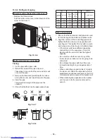
Wiring connection
The dashed lines show on-site wiring.
L
N
1
2
3
1
2
3
(Main circuit)
(Indoor/outdoor
connecting wires)
Outdoor unit
Remote
controller
Indoor unit
Earth
Leakage breaker
Input power
Fig. 10-5-14
Connect the indoor/outdoor connecting wires to
the identical terminal numbers on the terminal
block of each unit.
Incorrect connection may cause a failure.
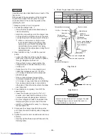
1. Remove the service valve cover from the outdoor
unit.
2. Remove the cord clamp.
3. Connect the power cord and the connecting
cable to the terminal as identi
fi
ed by the matching
numbers on the terminal block of indoor and
outdoor unit.
4. Secure the power cord and the connecting cable
with the cord clamp.
5. Attach the service valve cover on the outdoor
unit.
Stripping length of connecting cable for
outdoor unit
30
30
10
L N
10
1 2 3
10
10
40
40
Earth line
Connecting
cable
Power cord
Earth line
Fig. 10-5-15
•
•
•
1
2
3
1
2
3
L
N
Terminal block
Power cord
Connecting
cable for unit A
Connecting
cable for unit B
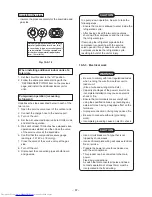
Fig. 10-5-16
10-5-4. Grounding
This air conditioner must be grounded without
fail.
Grounding is necessary not only to safeguard
against the possibility of receiving an electric
shock but also to absorb both the static, which
is generated by high frequencies and held in the
surface of the outdoor unit, and noise since the air
conditioner incorporates a frequency conversion
device (called an inverter) in the outdoor unit.
If the air conditioner is not grounded, users may
receive an electric shock if they touch the surface
of the outdoor unit and that unit is charged with
static.
•
•


