background image

4

REQUIREMENT OF REPORT TO THE LOCAL POWER SUPPLIER

Please make absolutely sure that the installation of this appliance is reported to 
the local power supplier before installation. If you experience any problems or if the 
installation is not accepted by the supplier, the service agency will take adequate 
countermeasures.


Important information regarding the refrigerant used

  This product contains 

fl

 uorinated greenhouse gases. 

  Do not vent gases into the atmosphere.
 Refrigerant 

type: 

R32

 GWP

(1)

 value: 

675

 * (ex. R32 ref. AR4)


(1)

GWP = global warming potential

  The refrigerant quantity is indicated on the unit name plate.
  * This value is based on F gas regulation 517/2014 

CAUTION

• Exposure of unit to water or other moisture before installation could result in 

electric shock.

  Do not store it in a wet basement or expose to rain or water.
• After unpacking the unit, examine it carefully for possible damage.
• Do not install the unit at place where leakage of 

fl

 ammable gas may occur. In 

case gas leaks and accumulates at surrounding of the unit, it may cause of 

fi

 re.

• Do not install in a place that can increase the vibration of the unit. Do not 

install in a place that can amplify the noise level of the unit or where noise and 
discharged air might disturb neighbors.

• To avoid personal injury, be careful when handling parts with sharp edges.
• Please read this installation manual carefully before installing the unit. It contains 

further important instructions for proper installation.

• The manufacturer shall not assume any liability for the damage caused by not 

observing the description of this manual.

Summary of Contents for RAS-M10PKVPG-E

Page 1: ...R CONDITIONER MULTIPLE TYPE INSTALLATION MANUAL 1121451199 R32 ENGLISH ESPAÑOL FRANÇAIS ITALIANO DEUTSCH PORTUGUÊS POLSKI ČESKY HRVATSKI MAGYAR NEDERLANDS ΕΛΛΗΝΙΚΑ SVENSKA SUOMI NORSK DANSK ROMÂNĂ БЪЛГАРСКИ EESTI LATVISKI SLOVENČINA SLOVENŠČINA LIETUVIŲ PУCСКИЙ ...

Page 2: ...ole and Mounting Installation Plate 7 Piping and Drain Hose Installation 8 Indoor Unit Fixing 9 In case of Indoor unit is fixed to Installation plate with screws 9 Drainage 9 ELECTRICAL WORKS 10 Wiring Connection 10 Connecting Cable Connection 11 OTHERS 12 Gas Leak Test 12 Remote Control A B Selection 12 Test Operation 12 Auto Restart Setting 12 CONTENTS EN ...

Page 3: ...oes not require admission or repeated hospital treatment 2 Property damage means greater damage which affects assets or resources For general public use Power supply cord and connecting cable of appliance use shall be at least polychloroprene sheathed flexible cord design H07RN F or cord designation 60245 IEC66 Shall be installed in accordance with national wiring regulations This appliance must b...

Page 4: ...ELECTRIC PARTS MAY BE DAMAGED CHECK THE EARTH WIRE THAT IT IS NOT BROKEN OR DISCONNECTED BEFORE INSTALLATION DO NOT INSTALL NEAR CONCENTRATIONS OF COMBUSTIBLE GAS OR GAS VAPORS FAILURE TO FOLLOW THIS INSTRUCTION CAN RESULT IN FIRE OR EXPLOSION TO PREVENT OVERHEATING THE INDOOR UNIT AND CAUSING A FIRE HAZARD PLACE THE UNIT WELL AWAY MORE THAN 2 M FROM HEAT SOURCES SUCH AS RADIATORS HEATERS FURNACE ...

Page 5: ...d possibly result in explosion and injury Thickness of copper pipes used R32 must be more than 0 8mm Never use copper pipes thinner than 0 8mm Do not perform flare connection inside a building or dwelling or room when joining the heat exchanger of indoor unit with interconnection piping Refrigerant connection inside a building or dwelling or room must be made by brazing or welding Joint connection...

Page 6: ...ter or other moisture before installation could result in electric shock Do not store it in a wet basement or expose to rain or water After unpacking the unit examine it carefully for possible damage Do not install the unit at place where leakage of flammable gas may occur In case gas leaks and accumulates at surrounding of the unit it may cause of fire Do not install in a place that can increase ...

Page 7: ...ipple 1 for heating model only 8 Cap water proof 2 for some models only 9 Owner s Manual Installation Manual B Label 2 for Multi model The part may differ from that shown The number of parts may differ by model The part is packed with the outdoor unit Filter Clean Replacement Air filters Clean every 2 weeks 1 Open the air inlet grille 2 Remove the air filters 3 Vacuum or wash and then dry them 4 R...

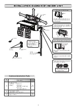
Page 8: ...d wall and tilt the indoor unit for better operation For the rear left and left piping Wall 1 Batteries Flat head wood screw Remote control holder Vinyl tape Apply after carrying out a drainage test Wireless remote control Shield pipe Attach to the front panel Air filter Hook Installation plate Hook 52 mm or more 190 mm or more 225 mm or more Insulate the refrigerant pipes separately with insulati...

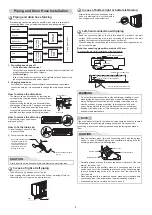
Page 9: ... a concrete wall with anchor bolts use the anchor bolt holes as illustrated in the below figure 3 Install the installation plate horizontally in the wall When installing the installation plate with a mounting screw do not use the anchor bolt holes Otherwise the unit may fall down and result in personal injury and property damage 1 After determining the pipe hole position on the mounting plate Æ dr...

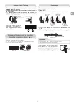
Page 10: ...fter passing the connecting pipe through the pipe hole connect the connecting pipes to the auxiliary pipes and wrap the facing tape around them Bind the auxiliary pipes two and connecting cable with facing tape tightly In case of leftward piping and rear leftward piping bind the auxiliary pipes two only with facing tape Indoor unit Connecting cable Auxiliary pipes Installation plate Carefully arra...

Page 11: ...age 1 Run the drain hose sloped downwards 2 Put water in the drain pan and make sure that the water is drained out of doors 3 When connecting extension drain hose insulate the connecting part of extension drain hose with shield pipe NOTE The hole should be made at a slight downward slant on the outdoor side Arrange the drain pipe for proper drainage from the unit Improper drainage can result in de...

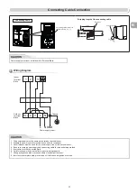
Page 12: ...l cords into the pipe hole on the wall 4 Take out the cable protrudes about 20 cm from the front 5 Insert the cable fully into the terminal block and secure it tightly with screws 6 Tightening torque 1 2 N m 0 12 kgf m 7 Secure the cable with the cord clamp 8 Fix the terminal cover and attach front panel to the indoor unit Cable about 20 cm Front panel Terminals block Main panel Terminal cover Wir...

Page 13: ...al Block Chassis CAUTION 1 The power supply must be same as the rated of air conditioner 2 Prepare the power source for exclusive use with air conditioner 3 Circuit breaker must be used for the power supply line of this air conditioner 4 Be sure to comply power supply and connecting cable for size and wiring method 5 Every wire must be connected firmly 6 Perform wiring works so as to allow a gener...

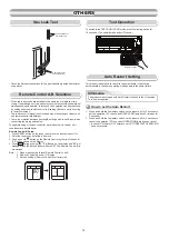
Page 14: ...r adjacent two rooms if operating a unit two units may receive the remote control signal simultaneously and operate In this case the operation can be preserved by setting either one remote control to B setting Both are set to A setting in factory shipment The remote control signal is not received when the settings of indoor unit and remote control are different There is no relation between A setti...

Reviews: