background image

– 60 –

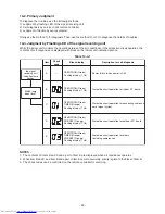
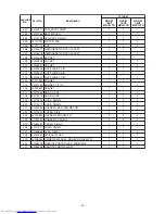
10-6-3. Indoor Unit (Other Parts)

e

r

u

d

e

c

o

r

p


g

n

i

k

c

e

h

C

e

m

a

n


t

r

a

P

.

o

N

1

Room temp. (TA) 

s

en

s

or 

He

a

t exch

a

nger (TC) 

s

en

s

or

Di

s

connect the connector 

a

nd me

asu

re the re

s

i

s

t

a

nce v

a

l

u

e with te

s

ter. 

(Norm

a

l temp.)

2

Remote controller

Refer to 10-5-1. (4).

3

Indoor f

a

n motor

Refer to 10-5-1. (

3

).

10°C

20°C

25°C

3

0°C

40°C

TA, TC (k

Ω

)

20.7

12.6

10.0

7.

9

4.5

Temperature

Sensor

Summary of Contents for RAS-M10U2MUVG-E

Page 1: ...FILE NO A10 1819 SERVICE MANUAL AIR CONDITIONER MULTI SPLIT TYPE INDOOR UNIT PRINTED IN JAPAN Apr 2018 ToMo Compact 4 way Cassette type RAS M10U2MUVG E TR RAS M13U2MUVG E TR RAS M16U2MUVG E TR ...

Page 2: ... VIEWS EXTERNAL VIEWS 17 5 WIRING DIAGRAMS 19 6 SPECIFICATIONS OF ELECTRICAL PARTS 20 7 REFRIGERANT CYCLE DIAGRAM 21 8 CONTROL BLOCK DIAGRAM 22 9 OPERATION DESCRIPTION 24 10 HOW TO DIAGNOSE THE TROUBLE 47 11 HOW TO REPLACE THE MAIN PARTS 61 12 EXPLODED VIEWS AND PARTS LIST 69 13 APPENDIX 77 ...

Page 3: ...ba Carrier Corporation or alternatively he or she has been instructed in such operations by an individual or individuals who have been trained and is thus thoroughly acquainted with the knowledge related to these operations The qualified installer who is allowed to do the electrical work involved in installation relocation and removal has the qualifications pertaining to this electrical work as st...

Page 4: ... illustrated mark describe the concrete mandatory contents Indicates cautions Including danger warning The sentences or illustration near or in an illustrated mark describe the concrete cautious contents Work undertaken All types of work Protective gloves Safety working clothing Gloves to provide protection for electricians Insulating shoes Clothing to provide protection from electric shock Helmet...

Page 5: ...erature parts You might get burned when removing this panel CAUTION Do not touch the aluminium fins of the unit Doing so may result in injury CAUTION BURST HAZARD Open the service valves before the operation otherwise there might be the burst WARNING ELECTRICAL SHOCK HAZARD Disconnect all remote electric power supplies before servicing WARNING Moving parts Do not operate unit with grille removed S...

Page 6: ...r the circuit breaker before proceeding with the work When you have noticed that some kind of trouble such as when a check code display has appeared there is a smell of burning abnormal sounds are heard the air conditioner fails to cool or heat or water is leaking has occurred in the air conditioner do not touch the air conditioner yourself but set the circuit breaker to the OFF position and conta...

Page 7: ... working at heights use a ladder which complies with the ISO 14122 standard and follow the procedure in the ladder fs instructions Also wear a helmet for use in industry as protective gear to undertake the work When working at heights put a sign in place so that no one will approach the work location before proceeding with the work Parts and other objects may fall from above possibly injuring a pe...

Page 8: ... and the service panel of the outdoor unit removed in order to find out exactly where the trouble lies place Keep out signs around the work site before proceeding Third party individuals may enter the work site and receive electric shocks if this warning is not heeded Connect the cut off lead wires with crimp contact etc put the closed end side upward and then apply a water cut method otherwise a ...

Page 9: ...tioner execute vacuuming and then newly recharge the specified amount of liquid refrigerant In this time never charge the refrigerant over the specified amount When recharging the refrigerant in the refrigerating cycle do not mix the other refrigerant into the specified refrigerant If air or others is mixed with the refrigerant abnormal high pressure generates in the refrigerating cycle resulted i...

Page 10: ...aused When the service panel of the outdoor unit is to be opened in order for the fan motor reactor inverter or the areas around these parts to be repaired immediately after the air conditioner has been shut down set the circuit breaker to the OFF position and then wait at least 10 minutes before opening the service panel If you fail to heed this warning you will run the risk of burning yourself b...

Page 11: ...he specifications in the installation manual and the stipulations in the local regulations and laws Install the circuit breaker where it can be easily accessed by the agent If you install the unit in a small room take appropriate measures to prevent the refrigerant from exceeding the limit concentration even if it leaks Consult the dealer from whom you purchased the air conditioner when you implem...

Page 12: ...y water leakage noise and or vibration may result When carrying out the pump down work shut down the compressor before disconnecting the refrigerant pipe Disconnecting the refrigerant pipe with the service valve left open and the compressor still operating will cause air etc to be sucked in raising the pressure inside the refrigeration cycle to an abnormally high level and possibly resulting in re...

Page 13: ...ken 416 8521 JAPAN More than H07RN F or 60245 IEC66 1 5 mm2 or more RBC UM21PG W E RBC AX32UM W E RB RWS21 E TCB SIR41UM E Ø9 52 Ø12 7 Manufacturer Connecting cable Option Ceiling panel Option Wireless remote controller kit Option Wired remote controller Option Occupancy sensor Conformity Standards E TR IEC EEN CE Mark LVD EEMC Certification RoHS WEEE ErP AS NZS RCM Mark IEC EEN CE Mark LVD EEMC C...

Page 14: ...re to check for leakage refrigerant or residual refrigerant If the leakage refrigerant comes into contact with fire a poisonous gas may occur or it may cause a fire Keep adequate ventilation during the work 4 When refrigerant gas leaks during work execute ventilation If the leakage refrigerant comes into contact with a fire a poisonous gas may occur or it may cause a fire 5 In places where install...

Page 15: ...igerant changes and then characteristics of the air conditioner change 3 Pipe Materials For the refrigerant pipes copper pipe and joints are mainly used It is necessary to select the most appropriate pipes to conform to the standard Use clean material in which impurities adhere inside of pipe or joint to a minimum 1 Copper pipe Be sure to select the pipes with copper thickness in the table below s...

Page 16: ...frigerant type may cause not only damage of the equipments but also a fire etc R410A tools available Partly unavailable R410A tools unavailable No Installation service tools Tools Equipment specification 1 Flare tool Clutch type Pipe flaring Use Applicability to R32 air conditioner or not Applicability to R22 air conditioner or not 5 Charge hose High voltage 3 Torque wrench Tightening of flare nut...

Page 17: ...l Space required for installation and servicing 1000 or more 1000 or more 15 or more 15 or more An obstacle or more 300 or less Indoor unit Stand up Bottom face of ceiling standing size Stand up 450 Check port 200 Hanging bolt M10 or W3 8 Procured by locally Hanging bolt pitch 535 Hanging bolt pitch 496 to 538 162 636 or less 850 or less 53 193 154 146 13 to 20 13 to 20 13 to 20 13 to 20 Bottom fa...

Page 18: ...00 or more 15 or more 15 or more An obstacle or more 300 or less Indoor unit Stand up Bottom face of ceiling standing size Stand up 450 Check port 200 Hanging bolt M10 or W3 8 Procured by locally Hanging bolt pitch 535 Hanging bolt pitch 496 to 538 162 636 or less 850 or less 53 193 154 146 13 to 20 13 to 20 13 to 20 13 to 20 Bottom face of ceiling 400 or more Note IF there is no ceiling board the...

Page 19: ...DC12V DC20V CN102 BLK CN101 CHK RED INDICATION WHT WHITE BLK BLACK YEL YELLOW Connector Parts Name BLU BLUE RED RED COLOR TCJ TC t t 7 BLK Indoor unit RED WHT 4 1 2 3 CN210 WHT 6 5 7 6 2 1 3 4 5 FM 1 20 19 18 12 9 1011 8 141516 13 CN510 WHT 17 CN104 1 1 2 WHT CN504 3 RED CN34 TA 4 1 2 3 5 7 6 9 8 WHT CN214 DM FS 7 LM1 6 2 1 5 3 4 5 20 19 18 12 9 1011 8 141516 13 17 LM3 5 LM2 5 LM4 5 4 1 2 3 5 7 6 ...

Page 20: ... M13 M16 Fan motor Louver motor Float switch Drain pump motor TA sensor TC sensor TCJ sensor ICF 340D60 1 MSBPC20F04 FS 0218 102 MDP 1401 Lead wire length 818 mm Vinyl tube Ø6 size lead wire length 500 mm Vinyl tube Black Ø6 size lead wire length 400 mm Vinyl tube Red ...

Page 21: ...erant flow Coolin g Refrigerant flow Heating Distributor Strainer incorporated Strainer TCJ sensor TC sensor Heat exchanger INDOOR UNIT Distributor Strainer incorporated Strainer TCJ sensor TC sensor Heat exchanger 7 REFRIGERANT CYCLE DIAGRAM RAS M10 13U2MUVG RAS M16U2MUVG The allowable pipe length charge amount of refrigerant and allowable height difference differ according to the outdoor unit to...

Page 22: ... Indoor fan motor CPU Driver DC12V DC5V DC20V Outside output Remote controller communication circuit Display LCD Function setup Key switch CPU Display LED Remote controller communication circuit Power circuit Power circuit Start Alarm DC280V Fan motor control circuit EEPROM TA sensor TC sensor TCJ sensor Float input HA Wireless Occupancy sensor Serial send receive circuit AC synchronous signal inp...

Page 23: ...Indoor fan motor Driver DC12V DC5V DC20V Remote controller communication circuit Power circuit DC280V Fan motor control circuit AC synchronous signal input circuit CPU EEPROM TA sensor TC sensor TCJ sensor Float input HA Wireless Occupancy sensor Serial send receive circuit LED Receiver Unit Outside output Start Alarm Wireless Remote Controller Kit ...

Page 24: ...After heat elimination 33 7 Intermittent Operation Control for Indoor Fans of the Indoor Unit at Thermo off Side in Heating Operation 34 8 Louver control 35 9 Filter sign display Except wireless type 38 10 DC motor 38 11 Drain pump delay operation 38 12 Occupancy sensor 38 13 Additional Operation 39 14 Remote A or B selection 40 15 Temporary operation 40 16 Short Timer 41 17 High ceiling select sw...

Page 25: ...indoor temperature and set temperature Correction along with variation of room temperature and correction of indoor heat exchanger temperature are added Temperature of indoor heat exchanger For these signals Operation mode Compressor revolution indoor heat exchanger temperature the outdoor unit controller monitors the input current to the inverter and performs the followed operation within the ran...

Page 26: ... remote controller ON OFF Operation selection COOL HEAT AUTO DRY FAN ONLY Temperature setup Air volume selection AUTO LOW LOW MED MED HIGH ECO COMFORT SLEEP ON timer setup QUIET OFF timer setup SWING Hi POWER PRESET ON OFF Operation flow and applicable data etc Description Indoor unit Command signal generating function of indoor unit operation Calculation function temperature calculation Activatio...

Page 27: ...ty is also given to operating mode of the indoor unit which was pressed first as same as the case when two indoor units are operated concurrently No Indoor unit Set operating mode Actual indoor unit operation Actual outdoor unit operation 1 4 Room temp control 1 Adjustment range Remote controller setup temperature C 2 Using the Item code FC 06 the setup temperature in heating operation can be corr...

Page 28: ...tion However the maximum frequency is limited to approximately S6 Note When LOW is set up the maximum frequency is lomited to approximately SB Operation flow and applicable data etc Description 1 6 Cooling Heating operation The operations are performed in the following parts by controls according to cooling heating conditions 1 Receiving the operation ON signal of the remote controller the cooling...

Page 29: ...C To 18 C To Trouble Correction value α 0K 1K 0K 1K 0K Cooling operation Cooling thermo OFF Fan only Setup air volume 1 The judgment of selecting COOL HEAT is carried out as shown below When 1 5 exceeds against Tsh 10 minutes and after thermo OFF heating operation Thermo OFF changes to cooling operation Description in the parentheses shows an example of cooling ON OFF When 1 5 lowers against Tsc 1...

Page 30: ...ses indicates one in AUTO cooling operation Value in the parentheses indicates one when thermostat of the remote controller works Value without parentheses indicates one when thermostat of the indoor unit works If the air speed has been changed once cannot be changed for 1 minute However when the air volume is changed the air speed also changes When heating operation has started follow the upward ...

Page 31: ...de for 1 minute after Tc entered in E zone of cool air discharge preventive control Selection of High ceiling type by changing CODE FC 5d or SW501 on P C board Operation flow and applicable data etc Description RAS M13U2MUVG E tap F1 F2 F3 F4 F5 F6 F7 F8 F9 FA FB FC FD COOL HH H H L L LL HEAT HH H H L L LL Standard 700 700 640 630 600 600 570 570 560 560 550 550 400 High Ceiling 1 N A N A N A N A ...

Page 32: ... of temperature and the room temperature the capacity is adjusted by the compressor revolution Remote controller Indoor unit Set temp Ts Room temp Ta 1 The difference between set temperature on remote controller Ts and room temperature Ta is calculated 2 According to the temperature difference the correction value of Hz signal which determines the compressor speed is set up 3 The rotating position...

Page 33: ...mmanded frequency is held When L zone is detected the commanded frequency is returned to the original value by approx 6Hz every 60 seconds Same status as that when thermostat OFF status that the air conditioner enters in the room temp monitor mode when the temperature reached the setup temperature on the remote controller Check code 0B NOTE When the operation has started or when Tc or Tcj 30 C at ...

Page 34: ...rred starts intermittent operation of the indoor fan The indoor fan operates with number of revolution of LL Fan ON time is 2 minutes and Fan OFF time is 2 to 4 minutes While heating operation is executed in two rooms if room temperature reached the setup temperature in both room had thermo off occurred both indoor units start intermittent operation of the indoor fan LL LL LL T off time To 5 C 2 m...

Page 35: ...ividually set or which position is locked fully closed when the unit stops and the louver is automatically set to horizontal discharge position when PRE HEAT Heating ready is displayed or during Themo off in heating operation Individual air direction setup In heating fan operation When louvers is in the swing mode they move further to the ceiling side than the preset position when swing mode is no...

Page 36: ...ndard Dual Cycle Selection of Swing mode can be set up by wired remote controller 1 Push the button to select 3 Louver setting on the menu screen then push the Set F2 button 2 Push the button to select 1 Swing type then push the Set F2 button 3 Push the button on the Swing type screen to select the swing type Refer to the Owner s Manual supplied with the indoor unit about the swing type 4 Push the...

Page 37: ...the button to select 2 Louver lock then push the Set F2 button 3 Push the Louver No F1 button to select the louver to set The display changes as follows each time the button is pushed 4 Push the button to select the louver wind direction Push the button to move the louver upward Push the button to move it downward Louver setting 1 Swing type 2 Louver lock Return Set Louver lock Return Fix Louver N...

Page 38: ...tops and a trouble is displayed Check code 11 12 Occupancy sensor 1 During the Occupancy sensor operation FC code B5 0001 and B6 0001 to 0005 when there is no people in the Occupancy sensor range it is automatically switched to the operation for the absence 2 The Occupancy sensor operation can change by FC code B6 as follows and operates according to the operation at absent time if time or absence...

Page 39: ...de is unable to work in dry mode 2 Quiet mode is appropriate to work with less cooling load and less heating load condition Because of the fan speed L may cause not enough the cooling capacity or heating capacity 3 ECO mode When pushing ECO button on the remote controller an Economic operation is performed 1 Temperature control Cooling operation The control target temperature increase 1 C per hour...

Page 40: ... shown below 1 Purpose This operation is to operate only one indoor unit using one remote controller 2 Description When operating one indoor unit in a situation where two indoor units have been installed in the same room or nearby rooms this operation prevents the remote controller signal from being received simultaneously by both units thus preventing both units from operating 3 Operation The ind...

Page 41: ... for 3 seconds 17 High ceiling select switch How to set the High ceiling switch Remove the cover of the electric parts box by taking off the mounting screws and pushing the hooking section There are the selector switches SW501 on the P C board of the electric parts box No 1 and No 2 of the selector switches SW501 are provided to select the height of the ceiling According to the ceiling height in t...

Page 42: ... automatically in the event of power supply being accidentally shut down When the unit is standby Not operating Operation Motions Push TEMPORARY button for more than three seconds Less than 10 seconds The unit is on standby The unit starts to operate The green indicator is on After approx three seconds release TEMPORARY button from being pushed The unit beeps three times and The green indicator fl...

Page 43: ...ower failure Operation Motions Push TEMPORARY button for more than three seconds Less than 10 seconds The unit is on standby The unit starts to operate The green indicator is on After approx three seconds release TEMPORARY button from being pushed The unit beeps three times and continues to operate If the unit is not required to operate at this time push TEMPORARY button once more or use the remot...

Page 44: ... heard 7 Set louver button FIX Push this button to adjust the airflow direction A receiving beep is heard It cannot be operated by holding down the button Push the button with some interval 8 Off timer button OFF Push this button to set the OFF timer 9 On timer button ON Push this button to set the ON timer 10 Reserve button SET Push this button to reserve time settings A receiving beep is heard 1...

Page 45: ...k time display The time set for timer operation or clock time is indicated The present time is always indicated except for TIMER operation 6 Hi POWER display Indicates when the high power operation starts Push the Hi POWER button to start and push it again to stop the operation 7 PRESET display Indicated when memorizing the preferred operation mode or when it has been memorized Also this icon is i...

Page 46: ...timer is reserved 6 lamp Orange In heating operation this lamp illuminates in the following cases The operation has started The temp controller has worked The unit is under defrost operation This lamp flashes while a trouble occurs CAUTION Disagreement in operation mode If pi pi sound is heard the display lamp goes on and the lamp and lamp flash alternately the operation is not performed with the ...

Page 47: ...ent 3 Judgment by Flashing LED of the signal receiving unit 4 Self Diagnosis by Remote Controller 5 Judgment of Trouble by Every Symptom No Troubleshooting Procedure 6 How to Check Simply the Main Parts 7 Troubleshooting 8 How to Diagnose Trouble in Outdoor Unit 9 How to Check Simply the Main Parts 10 How to Simply Judge Whether Outdoor Fan Motor is Good or Bad n o i t p i r c s e D r e n o i t i ...

Page 48: ...d when air conditioner operates 2 When item B and C and item B and a part of item E occur concurrently priority is given to the block of item B 3 The check codes can be confirmed on the remote controller for servicing Item Check code Block display Description for self diagnosis A OPERATION Green Flashing display 1 Hz Power failure when power is ON B OPERATION Green Flashing display 1 Hz Protective...

Page 49: ...troller Alphanumeric characters are used for the check codes is 5 is 6 is A is B is C is D Press ON or OFF button If there is no fault with a code the indoor unit will beep once Beep and the display of the remote controller will change as follows The TIMER indicator of the signal receiving unit flashes continuously 5 times per 1 sec Check the unit with all 52 check codes to as shown in Table 10 4 ...

Page 50: ... the indoor fan circuit All off Displayed when trouble is detected 1 Check the motor 2 When the motor is normal check P C board Float SW operation Operation continues Outdoor units stop Displayed when trouble is detected 1 Check the drainage 1 Amount of residual drain 2 Drain water piping installation situation 2 Float SW operation check 3 Check disconnection of connector Not displayed Trouble on ...

Page 51: ...trying operation again all operations stop immediately Replace P C board Being out of place disconnection or shortcircuit of the outdoor heat exchanger sensor TE or suction temp sensor Ts All off Displayed when trouble is detected 1 Check sensors TE TS 2 Check P C board Disconnection or shortcircuit of discharge temp sensor Td All off Displayed when trouble is detected 1 Check discharge temp senso...

Page 52: ...o gas leak 2 Unit operates normally during check If return serial signal does not stop between indoor terminal block 2 and 3 replace inverter P C board If signal stops between indoor terminal block 2 and 3 replace indoor P C board Compressor does not rotate Current protective circuit does not operate when a specified time passed after compressor had been activated All off Displayed when trouble is...

Page 53: ...te control NO NO NO YES YES YES Does transmission mark on remote control flash normally and is its signal transmitted properly YES Does transmission mark on remote control flash normally and is its signal transmitted properly Remote control is defective Operation Check item Conceivable principle cause Measure Item by symptoms Refer to 4 Troubleshooting for Remote Control Unit operates normally Is ...

Page 54: ...ough Indoor P C board is replaced Confirmation procedure Turn on power supply Does operation lamp flash Is wired correctly to white and black lead wires of terminal board Correct wiring To item of Power is not turned on YES NO YES NO ...

Page 55: ...ard correct Replace the indoor fan motor Model name for the indoor fan motor ICF 340D60 1 Checking procedure Measure the resistance of the following terminals with the tester Internal motor circuit is damaged if the measured value is out of the range in below table Measure by connecting the com side to 4 Black while measuring The measurement may vary Pin No Color Blue Yellow White Black Red Measur...

Page 56: ...door unit operate when moving remote control near receiver or indoor unit NO The unit does not beep at all OPERATION lamp on indoor unit is not indicated Is there any thyristor fluorescent light nearby NO YES YES NO YES YES NO Batteries are exhausted Is transmission mark indicated Does indoor unit start to operate by automatic restart function Does indoor unit beep and operate Does radio sound is ...

Page 57: ...rs on the P C board hold the whole housing Do not pull at the lead wire 2 Inspection procedures 1 When a P C board is judged to be defective check for disconnection burning or discoloration of the copper foil pattern or this P C board 2 The P C board consists of the following 2 parts a Main P C board part DC power supply circuit Indoor fan motor control circuit CPU and peripheral circuits buzzer b...

Page 58: ... seconds and they return to normal 3 seconds later The indicators are defective or the housing assembly CN214 is defective 5 Push button once to start the unit Shorten the restart delay timer Set the operation mode to COOL Set the fan speed level to AUTO Set the preset temperature much lower than the room temperature The unit compressor operates continuously in the above condition 1 Check whether ...

Page 59: ...perature C Resistance kΩ 10 C or above Indoor Outdoor inter unit cable CN67 DC fan output CN210 Louver CN510 Wireless remote control or Occupancy sensor CN214 White HA CN61 External input output UART CN521 DISP CN72 CHK CN71 Drain pump CN504 TA sensor CN104 TC sensor CN101 TCJ sensor CN102 Float SW CN34 Remote controller CN41 EEPROM IC503 11 6 2 P C Board Layout 1 Sensor characteristic table ...

Page 60: ...P o N 1 Room temp TA sensor Heat exchanger TC sensor Disconnect the connector and measure the resistance value with tester Normal temp 2 Remote controller Refer to 10 5 1 4 3 Indoor fan motor Refer to 10 5 1 3 10 C 20 C 25 C 30 C 40 C TA TC kΩ 20 7 12 6 10 0 7 9 4 5 Temperature Sensor ...

Page 61: ...lle from the ceiling panel while the air intake grille is opened 2 Attachment 1 Hook the hinge of the air intake grille to the main panel and then attach the fall preventive strap 2 Close the air intake grille and then slide the hook 3 Slide the grille fixing bracket to fix it with the screws Ø4 8 1pc d Electric parts cover 1 Detachment 1 Loosen the fixing screws 2 places of the electric parts cov...

Page 62: ...the louver motor connector of the ceiling panel so that it directs to the electric parts side and then hook the tentative hanging hook at the center part of the ceiling panel main body to the bell mouth 2 Connect the louver motor connectors at the ceiling panel side and the indoor unit side 3 Lift up the panel corner part and put out the screw head of the panel fixed implement Slide the panel fixe...

Page 63: ...g to the work in d 2 attach the electric parts covers as original h Turbo fan 1 Detachment 1 Remove the air intake grille Refer to 1 of c 2 Loosen the fix screws 2 positions of the bell mouth rotate the bell mouth and then take off it Ø4 10 2 pcs 3 Loosen the flange nut M8 at the center part of the turbo fan and then take off Counter clockwise Supporting with hands take off the turbo fan so that i...

Page 64: ...rain pan fixing bracket Ø4 8 4 pcs 7 Using the both hands hold the water spilling port part of the drain pan and then slowly pull out the foaming parts firstly As there is remained water in the drain pan clear it carefully 2 Attachment 1 Arrange direction of the drain pan directly to the foaming parts and insert it Pass the fan motor lead wire through the inner side of the drain pan 2 Attach the f...

Page 65: ...drain pump wiring through side plate and clamp and then connect the connector to the control P C board 4 Following to work in i 2 attach the drain pan panel and electrical parts covers as original k Float switch 1 Detachment 1 Remove the drain pan Refer to i 1 2 Remove the float switch connector CN34 3P Red connected to the control P C board and then take off the lead wires from the clamp 3 Remove...

Page 66: ...der and then tighten to fix them Tightening toque 4 9 0 5N m 2 Pass the lead wire through the motor lead wire fixing plate removed in 1 3 and then fix it with shoulder screw 3 Perform wiring of the motor lead wires as original connect the connector to the control P C board and then attach the wiring fixing plate and the wiring cover 4 Following to works in h 2 and d 2 attach the turbo fan and the ...

Page 67: ...move the screw of the TA sensor cover Ø4 10 1pc 4 Remove TA sensor from the TA sensor fixed implement 2 Attachment 1 Fix TA sensor to TA sensor fixing implement and fix the TA sensor cover with screw Ø4 10 1 pcs Ø4 8 1 pcs 2 Perform wiring of TA sensor as original Adjust position of the tube so that the tube of TA sensor will be included in the cover Fixing screw TA sensor cover TA sensor fixing b...

Page 68: ... exchanger so that it will not be fallen down Take note that you will not get hurt by touching to Aluminum fin Be sure to put on the protective gloves and the safety working clothing 2 Attachment 1 Attach the heat exchanger as original with the separate plate and the fixing plate 2 Slide the piping cover to the groove fix it to the side plate and then use the screws Ø4 8 3 pcs 3 Perform wiring of ...

Page 69: ...2MUVG E M16U2MUVG E 202 203 226 228 217 220 205 201 227 204 224 219 218 PRESET FAN MODE QUIET SWING SLEEP COMFORT FIX HI POWER TIMER ON OFF CHK FILTER CLOCK TOSHIBA TEMP CLR SET SLEEP 221 222 225 206 207 216 211 210 212 213 208 209 223 214 215 229 230 TOSHIBA 231 ...

Page 70: ...66038 FAN ASSY TURBO BELL MOUTH PAN ASSY DRAIN MOTOR FAN NUT REFRIGERATION CYCLE ASSY REFRIGERATION CYCLE ASSY SOCKET SOCKET SOCKET NUT FLARE 1 4 IN NUT FLARE 3 8 IN NUT FLARE 1 2 IN BONNET BONNET 1 2 IN BONNET BAND HOSE BAND HOSE HOSE DRAIN HOSE DRAIN HOLDER LEAD FAN MOTOR COVER PIPE HOLDER SENSOR TS RUBBER CUSHION COVER E BOX PUMP DRAIN LEAD RELAY SWITCH FLOAT OWNER S MANUAL RAS M1OU2UVG E REMOT...

Page 71: ...G TR 202 203 226 228 217 220 205 201 227 204 224 219 218 PRESET FAN MODE QUIET SWING SLEEP COMFORT FIX HI POWER TIMER ON OFF CHK FILTER CLOCK TOSHIBA TEMP CLR SET SLEEP 221 222 225 206 207 216 211 210 212 213 208 209 223 214 215 229 230 TOSHIBA 231 ...

Page 72: ...6038 FAN ASSY TURBO BELL MOUTH PAN ASSY DRAIN MOTOR FAN NUT REFRIGERATION CYCLE ASSY REFRIGERATION CYCLE ASSY SOCKET SOCKET SOCKET NUT FLARE 1 4 IN NUT FLARE 3 8 IN NUT FLARE 1 2 IN BONNET BONNET 1 2 IN BONNET BAND HOSE BAND HOSE HOSE DRAIN HOSE DRAIN HOLDER LEAD FAN MOTOR COVER PIPE HOLDER SENSOR TS RUBBER CUSHION COVER E BOX PUMP DRAIN LEAD RELAY SWITCH FLOAT OWNER S MANUAL RAS M1OU2UVG TR REMOT...

Page 73: ...Q ty Set RAS M 16U2MUVG E 401 402 403 404 405 406 407 408 409 43050425 43160565 43160568 4316V660 4316V663 4316V664 43F50426 43163057 43163058 SENSOR ASSY SERVICE TC F6 TERMINAL BLOCK 3P 20A TERMINAL 2P PC BOARD ASSY PC BOARD ASSY PC BOARD ASSY SENSOR SERVICE TA CLAMP DOWN CLAMP UP 2 1 1 1 1 1 1 13U2MUVG E 2 1 1 1 1 1 1 10U2MUVG E 2 1 1 1 1 1 1 16U2MUVG TR 13U2MUVG TR 10U2MUVG TR Description ...

Page 74: ...3109441 43180361 4342D001 43107296 43107297 43122166 4310A142 4310A143 43107298 43107299 43107300 43107301 43107302 43107303 43160664 4310A144 43419022 43107304 43107305 GRILLE AIR INLET AIR FILTER MOTOR LOUVER MSBPC20F04 OUTLET AIR FORM OUTLET AIR FORM LOUVER ASSY COVER PANEL ASSY COVER PANEL ASSY PLATE FIX PANEL A PLATE FIX PANEL B HOOK CAP AXIS FIX MOTOR ASSY FIX MOTOR ASSY LEAD MOTOR PANEL HIN...

Page 75: ...No Q ty Set RBC AX32UM W E Part No Description 351 352 353 354 355 356 357 4316V616 43162088 43108036 43160665 43408061 43166018 43F83071 PC BOARD ASSY REMOTE RECIEVER COVER WRS COVER PANEL WRS LEAD COVER WIRELESS REMOTE CONTROLLER WIRELESS WH L11SE HOLDER REMOTE CONTROLLER 1 1 1 1 1 1 1 ...

Page 76: ...r TCB SIR41UM E 362 364 365 361 363 Location No Q ty Set TCB SIR41UM E Part No Description 361 362 363 364 365 43162088 43108037 43160666 43408062 43469067 COVER WRS COVER PANEL WRS LEAD COVER SENSOR THERMOSTAT 1 1 1 1 1 ...

Page 77: ...de Fan Speed Cool Test 2 Room A 12 00 Return Test mode stop No Yes Test mode 3 1 Push the button to select 1 Test mode on the Field setting menu screen then push the Set F2 button Pushing the Yes Yes F1 button sets the test mode and the screen returns to the Field setting menu screen Push CANCEL twice the screen 2 appears 2 Push the ON OFF button to start the test mode The screen 1 shown in the le...

Page 78: ...tting menu screen then push the Set F2 button The fan of the indoor unit operate Move the cursor to select Function code with the F1 button then set Function code with the button Move the cursor to select data with the F2 button then set data with the button 2 Refer to the Installation Manual supplied with the indoor unit or service manual for details about the Function code and data 3 Push the ME...

Page 79: ...selection 0000 A 0001 B 0000 A F0 Swing mode 0001 Standard 0003 Cycle swing 0002 Dual swing 0001 Standard F1 Louver fixed position Louver No 1 0000 Release 0005 Downward discharge position 0001 Horizontal discharge position 0000 Not fixed F2 Louver fixed position Louver No 2 0000 Release 0005 Downward discharge position 0001 Horizontal discharge position 0000 Not fixed F3 Louver fixed position Lou...

Page 80: ...on current 1 10 A 70 Compressor operation frequency rps 72 Outdoor fan revolution frequency rpm F1 Compressor calculated operation time 100h Outdoor unit data 4 Alarm history List of latest 10 alarm data trouble information of check code date time and unit is displayed 1 Test mode 2 Register service info 3 Alarm history 4 Monitor function 5 Setting louver position Field setting menu 1 2 Return Set...

Page 81: ...TOSHIBA CARRIER CORPORATION 72 34 Horikawa cho Saiwai ku Kawasaki shi Kanagawa 212 8585 JAPAN Copyright 2018 TOSHIBA CARRIER CORPORATION ALL Rights Reserved ...

Reviews: