– 35 –
9-8-1. Check and Test Operation
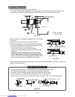
Be sure to test the piping connections for gas leaking.
• Check the flare nut connections, valve stem cap
connections and service port cap connections for
gas leak with a leak detector or soap water.
9-8-2. Setup of Selector Switch on Switch Panel
Temporary switch
For an temporary operation when the remote
controller is not found or in a trial operation, set
the TEMPORARY switch to COOL or AUTO side.
If setting the switch to COOL side, the cooling
operation can be confirmed even while the
thermostat is OFF when temperature of the return
air is low.
Auto Restart switch
The Auto Restart switch is useful for restarting the
system when the outside power supply is un-
stable by an instantaneous power failure, etc. Do
not use this switch when the unit itself is in
trouble.
Using VOLTAGE1 and VOLTAGE2 switches, select
an appropriate voltage according to supplied
voltage. Voltage, 220V, 230V, or 240V can be
selected.
REMOCON priority select switch
When the indoor units are nearly set, set both
indoor unit and remote controller to A or B for
selecting the priority.
Remote controller sensor
The remote controller sensor can receive a signal
at position approx. 7m off.
Operation lamp
This lamp goes on during operation, and goes off
during stop time, respectively.
Fig. 9-8-3
Fig. 9-8-4
• Service port cap connection
• Valve stem cap connection
Flare nut
connections
(Outdoor unit)
Flare nut
connections
(Indoor unit)
2 2 0 V / 2 3 0 V
2 4 0 V
2 2 0 V
2 3 0 V
A
B
AUTO RESTART
OFF ON
TEMPORARY
COOL AUTO
VOLTAGE1
VOLTAGE2
REMOCON
Voltage select switch
3
Remote controller select
4
Auto Restart switch
2
Remote controller sensor
5
Operation lamp
6
Temporary switch
1
Summary of Contents for RAS-M10YDCV-E
Page 62: ......


