background image

i

1 SAFETY PRECAUTIONS  ..............................................1
2 OPTIONAL PARTS, ACCESORIES AND TOOLS  ........3
3 WHICH MODELS CAN BE COMBINED ........................5
4 INSTALLATION OF OUTDOOR UNIT ...........................6
5 GROUNDING ...............................................................11
6 CHECK AND TEST OPERATION  ...............................11
7 USEFUL FUNCTIONS .................................................12

1 MESURES DE SECURITE  ............................................1
2 PIECES EN OPTION, ACCESSOIRES ET OUTILS  .....3
3 QUELS MODELES PEUVENT ETRE COMBINES  .......5
4 SYSTEME DE PRIORITES DE MODE DE 

FONCTIONNEMENT .....................................................6

5 MISE A LA TERRE  ......................................................11
6 CONTROLE ET OPERATION D’ESSAI  ......................11
7 FONCTIONS UTILES  ..................................................12

1 SICHERHEITSVORKEHRUNGEN ................................1
2 SONDERTEILE, SONDERZUBEHÖR UND 

WERKZEUGE ................................................................3

3 WELCHE MODELLE KÖNNEN KOMBINIERT 

WERDEN .......................................................................5

4 INSTALLATION DES AUSSENGERÄTS  ......................6
5 ERDUNG .....................................................................11
6 PRÜFUNG UND TESTBETRIEB .................................11
7 NÜTZLICHE FUNKTIONEN  ........................................12

1 PRECAUZIONI PER LA SICUREZZA  ...........................1
2 COMPONENTI OPZIONALI, ACCESSORI E 

STRUMENTI ..................................................................3

3 QUALI MODELLI É POSSIBILE COMBINARE  .............5
4 INSTALLAZIONE DELL’UNIT À ESTERNA  ..................6
5 MESSA A TERRA ........................................................11
6 CONTROLLI E FUNZIONAMENTO DI PROVA  ..........11
7 FUNZIONI UTILI  ..........................................................12

1 PRECAUCIONES SOBRE SEGURIDAD  ......................1
2 PARTES OPCIONALES, ACCESORIOS Y 

HERRAMIENTAS ..........................................................3

3 QUÉ MODELOS PUEDEN COMBINARSE  ...................5
4 INSTALLATION DE LA UNIDAD EXTERIOR ................6
5 CONEXIÓN A TIERRA  ................................................11
6 COMPROBACIÓN Y OPERACIÓN DE PRUEBA  .......11
7 FUNCIÓN PRÁCTICA  .................................................12

1 PRECAUÇÕES DE SEGURANÇA ................................ 1
2 PEÇAS OPCIONAIS, ACESSÓRIOS E 

FERRAMENTAS ........................................................... 3

3 MODELOS QUE PODEM SER COMBINADOS ............ 5
4 INSTALAÇÃO DA UNIDADE EXTERIOR  ..................... 6
5 LIGAÇÃO À TERRÀ  .................................................... 11
6 VERIFICAÇÃO E TESTE DA OPERAÇÃO  ................. 11
7 FUNÇÕES ÚTEIS  ....................................................... 12

1

ΠΡΟΦΥΛΑΞΕΙΣ


ΑΣΦΑΛΕΙΑΣ


....................................... 1

2

ΠΡΟΑΙΡΕΤΙΚΑ


ΑΝΤΑΛΛΑΚΤΙΚΑ

ΕΞΑΡΤΗΜΑΤΑ


ΚΑΙ


ΕΡΓΑΛΕΙΑ


..................................................................... 3

3

ΠΟΙΑ


ΜΟΝΤΕΛΑ


ΜΠΟΡΟΥΝ


ΝΑ


ΣΥΝ∆ΥΑΣΤΟΥΝ


...... 5

4

ΕΓΚΑΤΑΣΤΑΣΗ


ΕΞΩΤΕΡΙΚΗΣ


ΜΟΝΑ∆ΑΣ


................... 6

5

ΓΕΙΩΣΗ


........................................................................ 11

6

ΕΛΕΓΧΟΣ


ΚΑΙ


∆ΟΚΙΜΗ


ΛΕΙΤΟΥΡΓΙΑΣ


...................... 11

7

ΧΡΗΣΙΜΕΣ


ΛΕΙΤΟΥΡΓΙΕΣ


.......................................... 12

1 МЕРЫ ПРЕДОСТОРОЖНОСТИ 

................................. 1

2 ДОПОЛНИТЕЛЬНЫЕ ЧАСТИ, 

ПРИНАДЛЕЖНОСТИ И ИНСТРУМЕНТЫ 

.................. 3

3 КОМБИНАЦИЯ КАКИХ МОДЕЛЕЙ ВОЗМОЖНА 

...... 5

4 УСТАНОВКА НАРУЖНОГО БЛОКА 

........................... 6

5 ЗАЗЕМЛЕНИЕ 

............................................................ 11

6 ПРОВЕРКА И ТЕСТОВАЯ ЭКСПЛУАТАЦИЯ 

.......... 11

7 УДОБНАЯ ФУНКЦИЯ 

................................................ 12

CONTENTS/SOMMAIRE/INHALT/INDICE/ÍNDICE/ÍNDICE/

ΠΕΡΙΕΧΟΜΕΝΑ

/

СОДЕРЖАНИЕ

ENGLISH

FRANÇAIS

DEUTSCH

ITALIANO

ESPAÑOL

PORTUGUÊS

ΕΛΛΗΝΙΚΗ

Русский язык

OutdoorInstallation.book  Page i  Wednesday, February 1, 2006  9:12 AM

Summary of Contents for RAS-M14GACV-E

Page 1: ...ΟΝΑ Α ΠΟΛΛΑΠΛΟΥ ΤΥΠΟΥ Για γενική δηµόσια χρήση КОНДИЦИОНЕР МУЛЬТИ РАЗДЕЛИТЕЛЬНОГО ТИПА Для общего бытового использования Outdoor Unit Unité extérieure Außengerät Unità esterna Unidad exterior Unidade exterior Εξωτερική µονάδα Наружный блок RAS M14GAV E RAS M18GAV E RAS M14GACV E RAS M18GACV E Please read this installation manual carefully before installing the air conditioner Veuillez lire attenti...

Page 2: ...SOBRE SEGURIDAD 1 2 PARTES OPCIONALES ACCESORIOS Y HERRAMIENTAS 3 3 QUÉ MODELOS PUEDEN COMBINARSE 5 4 INSTALLATION DE LA UNIDAD EXTERIOR 6 5 CONEXIÓN A TIERRA 11 6 COMPROBACIÓN Y OPERACIÓN DE PRUEBA 11 7 FUNCIÓN PRÁCTICA 12 1 PRECAUÇÕES DE SEGURANÇA 1 2 PEÇAS OPCIONAIS ACESSÓRIOS E FERRAMENTAS 3 3 MODELOS QUE PODEM SER COMBINADOS 5 4 INSTALAÇÃO DA UNIDADE EXTERIOR 6 5 LIGAÇÃO À TERRÀ 11 6 VERIFICA...

Page 3: ...dust former refrigerant or refrigeration machine oil does not enter into the new type refrigerant R410A air conditioner circuit To prevent mixing of refrigerant or refrigerating machine oil the sizes of connecting sections of charging port on main unit and installation tools are different from those used for the conventional refrigerant units Accordingly special tools are required for the new refr...

Page 4: ...L CAUSE AIR ETC TO BE SUCKED IN RAISING THE PRESSURE INSIDE THE REFRIGERATION CYCLE TO AN ABNORMALLY HIGH LEVEL AND POSSIBLY RESULTING IN RUPTURING INJURY ETC WHEN CARRYING OUT THE PUMP DOWN WORK SHUT DOWN THE COMPRESSOR BEFORE DISCONNECTING THE REFRIGERANT PIPE DISCONNECTING THE REFRIGERANT PIPE WITH THE SERVICE VALVE LEFT OPEN AND WITH THE COMPRESSOR STILL OPERATING WILL CAUSE AIR ETC TO BE SUCK...

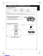
Page 5: ...utdoor unit Secure the outdoor unit with the attachment bolts and nuts if the unit is likely to be exposed to a strong wind Use φ8 mm or φ10 mm anchor bolts and nuts If it is necessary to drain the defrost water attach drain nipple to the base plate of the outdoor unit before installing it Accessory and Installation Parts Part No Part name Q ty Part No Part name Q ty a Outdoor unit installation ma...

Page 6: ...rs have been changed Charge hose In order to increase pressure resisting strength hose materials and port sizes have been changed to 1 2 UNF 20 threads per inch When purchasing a charge hose be sure to confirm the port size Electronic balance for refrigerant charging As working pressure is high and gasification speed is fast it is difficult to read the indicated value by means of charging cylinder...

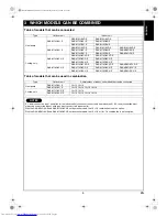
Page 7: ...10GKCV E RAS M13GKCV E RAS M16GKCV E RAS M10GDCV E RAS M13GDCV E RAS M16GDCV E Type Outdoor unit Combinations of indoor unit models that can be connected Heat pump RAS M14GAV E 10 10 10 13 RAS M18GAV E 10 10 10 13 10 16 13 13 Cooling only RAS M14GACV E 10 10 10 13 RAS M18GACV E 10 10 10 13 10 16 13 13 NOTES A 1 room connection is not an option for the indoor units you cannot connect only one indoo...

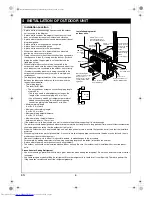
Page 8: ...s sturdy enough The platform should be designed and manufactured to maintain its strength over a long period of time and sufficient consideration should be given to ensuring that the outdoor unit will not fall When the outdoor unit is to be mounted high on a wall take particular care to ensure that parts do not fall and that the installer is protected When doing installation work at ground level i...

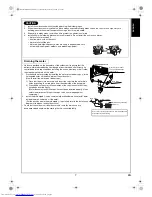
Page 9: ...he drain nipple c is installed refer to the installation diagram of the indoor and outdoor units Check that the outdoor unit is horizontal and route the drain hose at a downward sloped angle while ensuring that it is connected tautly CAUTION 1 Install the outdoor unit without anything blocking the discharging air 2 When the outdoor unit is installed in a place always exposed to strong winds like o...

Page 10: ...rigerant Piping Connection Outer diameter of copper pipe R410A tool used Conventional tool used 6 35 0 to 0 5 1 0 to 1 5 9 52 0 to 0 5 1 0 to 1 5 12 7 0 to 0 5 1 0 to 1 5 Outer diameter of copper pipe R410A 6 35 1 5 to 2 0 9 52 1 5 to 2 0 12 7 2 0 to 2 5 Outer diameter of copper pipe B R410A R22 6 35 9 1 9 0 9 52 13 2 13 0 12 7 16 6 16 2 CAUTION Do not apply excessive force Otherwise the nut may b...

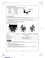
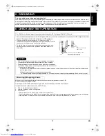
Page 11: ...15 minutes if the piping length is 20 meters 15 minutes for 20 meters assuming a pump capacity of 27 liters per minute Confirm that the compound pressure gauge reading is 101 kPa 76 cmHg 5 Close the low pressure valve handle of gauge manifold 6 Open fully the valve stem of the packed valves both sides of Gas and Liquid 7 Remove the charging hose from the service port 8 Securely tighten the caps on...

Page 12: ...reaker or fuse all types can be used Power cord H07RN F or 60245IEC66 1 5 mm2 Connecting cable H07RN F or 60245IEC66 1 0 mm2 CAUTION Incorrect wiring connection may cause electrical parts to burn out Be sure to comply with local regulations codes when running the wire from outdoor unit to indoor unit Size of wire and wiring method etc Every wire must be securely connected If incorrect or incomplet...

Page 13: ...rotective devices specified in this manual Insulate the unused cords conductors with PVC tape 1 Turn on the electrical power breaker 2 Operate the indoor unit in cooling mode 3 Start checks Run the indoor unit in room A and confirm cool air blows out Confirm the indoor unit in room B is not running Also check at this time that refrigerant which can be heard is not flowing Stop operation of the ind...

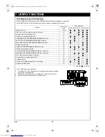
Page 14: ... running None IGBT short circuit Compressor motor rear short 14 Trouble on position detecting circuit 16 Trouble on current detecting circuit 17 CONDENSOR PIPE TEMPERATURE SENSOR TE fault 18 SUCTION PIPE TEMPERATURE SENSOR TS fault 18 DISCHARGE PIPE TEMPERATURE SENSOR TD fault 19 Trouble on outdoor fan 1A OUTDOOR TEMPERATURE SENSOR TO fault 1B Trouble on compressor system 1C GAS SIDE PIPE TEMPERAT...

Page 15: ...EG32906701 a 00_OutdoorInstallation_BCO fm Page 2 Wednesday February 1 2006 10 54 AM ...

Reviews: