background image

~ 115 ~

~ 115 ~

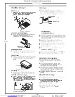
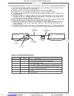
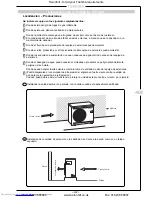
Stellen Sie sicher, daß das Netzkabel und das Kabel für die Steuerung des Systems nicht mit
Ventilen oder Rohrleitungen, die nicht isoliert sind, in Kontakt kommen.

Vorsichtsmaßnahmen

Nach beendeter Installation sicherstellen, daß alle Stromzufuhr- und Verbindungsanschlüsse
entsprechend geschützt sind.

Elektrische Verdrahtung

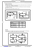
Nach Verlegen der Kühl- und Ablaufrohre sicherstellen, daß alle Rohre komplett isoliert und die
Isolierung mit Isolierband versiegelt ist.

Kühlrohre

U

MWELT

Vorsichtsmaßnahmen für den Fall eines Kältemittelaustritts

L

ETZTE

I

NSTALLATIONSÜBERPRÜFUNGEN

!

!

!

!

!

!

!

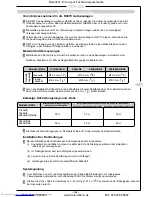
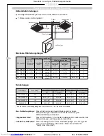
Diese Klimaanlage enthält HFC-407C Kältegas. Wir empfehlen, daß der Installateur die
Gesamtmenge des Kältemittels im System mit dem Luftvolumen jedes Raums, in dem eine
Innenanlage installiert ist, vergleicht. Dies ist besonders dann wichtig, wenn ein System mit
großem Kältemittelvolumen installiert wird. Errechnen Sie unter Verwendung dieser Zahlen
die schlimmste anzunehmende Kältemitteldichte (unter Berücksichtigung der
Gesamtkältemittelmenge) für den unwahrscheinlichen Fall eines Lecks. Wenn die sich hier-
bei ergebenden Dichte den Standardwert überschreitet, dann muß entweder ein
Entlüftungs- oder ein Alarmsystem oder beides installiert werden. Hierbei sind örtliche,
nationale und internationale Normen, Vorschriften und Bestimmungen zu berücksichtigen.

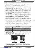
WARTUNG DER KLIMAANLAGE
Um die Möglichkeit einer Beschädigung der Klimaanlage möglichst auszuschließen sowie
um ihren störungsfreien Betrieb zu gewährleisten, empfehlen wir, die Anlage regelmäßig von
einem entsprechend qualifizierten Fachmann warten zu lassen.

Hinweise zur Entsorgung

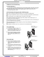
Eine Klimaanlage ist stets umweltgerecht zu entsorgen. Am besten ist natürlich Recycling.

Informationen zur umweltgerechten Entsorgung einer Klimaanlage erhalten Sie vom
Hersteller, von Ihrem zuständigen Umweltamt oder vom nächsten Recyclinghof.

Stellen Sie sicher, daß alles Verpackungsmaterial recycelt bzw. korrekt entsorgt wird.

Das Kältemittel in der Anlage darf nur durch ein entsprechend qualifiziertes Unternehmen
abgelassen werden.

ACHTUNG: Das Ablassen von Kältemittel in die Atmosphäre ist verboten und wird
strafrechtlich verfolgt.

D

Heronhill - for all your Toshiba requirements

Tel: 01823 665660

www.heronhill.co.uk

Fax: 01823 665807

Summary of Contents for RAV-104 Series

Page 1: ... PE RAV 164A PE KUHLMODELL RAV 264B C K U PE RAV 264A A8 PE TIPO A REFRIGERAZIONE RAV 364B C U PE RAV 364A8 PE MODELO REFRIGERANTE RAV 464B C U PE RAV 464A8 PE KOELING MODEL HFC AIR CONDITIONER SPLIT TYPE SYSTEM CONDITIONNEUR D AIR TYPE SPLIT SYSTEM KLIMAANLAGE GETEILTE BAUWEISE ACONDICIONADOR DE AIRE TIPO SPLIT CONDIZIONATORE D ARIA TIPO SPLIT AIRCONDITIONER SPLIT MODEL INSTALLATION INSTRUCTIONS ...

Page 2: ...ctro Magnetic Compatibility Accordingly they are designated for use in commercial and industrial environments OPERATING CONDITIONS KEY TO MODEL NAMES Throughout this booklet various types of indoor units will be referred to by model codes Details are shown in the table below UNIT DESCRIPTION HEAT PUMP CODE COOLING ONLY CODE BUILT IN DUCT TYPE BH SBH B CEILING TYPE CH WIRED REMOCON CHR INFRARED REM...

Page 3: ... AI Room Remote Controller Flush Wall Mounting Wall Surface Mounting 31 32 Location of Infra Red Remote Controller Installing the Infra Red Remote 33 Infra Red Remote Controller Mounting 33 Improving System Efficiency Air Flow Adjustment Increasing Heating Effect 33 Heat Pump Twin Set up 34 35 Cooling Only Twin Kit Set up 36 38 Final Installation Checks Environmental Issues 39 E I NL D F GB Passer...

Page 4: ...ulating the pipe connections Cardboard template 1 For installation of the cassette and ceiling panel Bolt M5 x 20mm 4 To secure the panel to the cassette UH U Units DESCRIPTION QUANTITY DIAGRAM APPLICATION Pipe insulation 2 For insulating the pipe connections Cardboard template 1 For installation of the cassette and ceiling panel Insulation block 4 164 264 For 2 directional and 2 364 464 3 directi...

Page 5: ...e weight of the outdoor unit Where the water drainage may cause a nuisance or a hazard when frozen Where strong winds may blow against the air outlet of the outdoor unit The high pressure switch could be tripped if a strong wind should blow against the air outlet during cooling operation Where this condition is likely to be present protect the outdoor unit against winds for example by Precautions ...

Page 6: ...piping space 500mm or more 300mm or more Air outlet facing the wall Do not allow units to be situated so that outlet air from one unit is discharged directly into the intake of another unit as indicated below Mounting Airflow Path Model A mm RAV 364AH8 A8 150 RAV 464AH8 A8 150 Remaining models 100 A mm or more see table below Wiring and piping space 500mm or more 3 7 300mm min A mm or more see tab...

Page 7: ...ubject to heavy snowfalls protect the outdoor unit from snow as follows i Install the unit on a stand which will keep the unit above the level of the standing snow ii The stand must facilitate water drainage iii Install snow protection hoods over the air intake and outlet Ensure that the airflow is not affected Failure to take adequate measures in this respect may result in the unit malfunctioning...

Page 8: ...ed air Location Precautions Good location Evenly cooled Bad location Oblique line area not well cooled Bad location Oblique line area not well cooled 7 7 3 If a good location is not possible use a fan to circulate the air evenly throughout the room UH U Units only Choose the number of airflows that are required depending on the shape of the room and the loca tion of the indoor unit Insulation Bloc...

Page 9: ...r more 30mm or more 300mm or more 500mm or more 400mm or more 150mm or more Provide an inspection hole in this position Inspection hole 150mm or more NH Units Minimum Upper Plate Duct Plate Minimum 60mm 25mm 20mm 140mm 65mm 90mm 150mm 100mm Drain Catch Fixing location to floor base 160mm 145mm Air Outlet 150mm Heronhill for all your Toshiba requirements Tel 01823 665660 www heronhill co uk Fax 018...

Page 10: ...0mm or more 400mm or more 500mm or more 150mm or more 600mm 600mm 600mm 200mm 15mm or more 1000mm or more Obstacle 1000mm or more Ceiling 1000mm or more Terminal box wiring connections Drain pipe connections Air Outlet Electrical box PCB transformer MF capacitor Heronhill for all your Toshiba requirements Tel 01823 665660 www heronhill co uk Fax 01823 665807 ...

Page 11: ...0 19 0 9 5 252 930 310 3 4 164BH B 700 750 780 12 7 6 4 252 280 280 1 2 264B 1000 1050 1080 15 9 9 5 252 580 290 2 3 Sliding bracket Reinforcing bar Foundation bolt Foundation bolt for hanging the piping Angular bracket for support Installation on a wooden structure Place a length of wood of the appropriate size across two beams and install the hanging bolts onto this length of wood Installation o...

Page 12: ...g Life Filter Kit is available as an optional accessory l The Filter Kit can be installed on either the lower or rear air inlet of the Duct Type unit l To connect square duct prepare the connection flange locally as shown below RAV 164BH B Supply Flanges RAV 264BH B RAV 364BH B RAV 464BH B Return Flanges RAV 164BH B RAV 264BH B RAV 364BH B RAV 464BH B Shelter Board C x Ø6 holes Supply duct local p...

Page 13: ...e Hanging Bolt Newly built concrete slab Install hanging bolts with inserts embedded bolts etc Wooden strutted room Install hanging bolts on a square wooden piece placed over beams Edge sharp insert Slide insert Embedded bolt of piping Reinforcing bar Installing Hexagon Bolt accessory Allow a spacing of about 10mm M8 x 25mm hexagon bolts 4 Determining installation position and direction of the pip...

Page 14: ... adjust it at this state 3 Hanging the Indoor Unit Fit the Hexagon bolts of the unit into slit grooves 4 Fasten the Hexagon bolts to hang the unit Remote Control Cord CH C Models only l Wire the cord over the refrigerant piping and the drain piping l If the cord was wired under the piping it would cause difficulty in pulling out the air filter Ceiling board 40mm or less Hanger Allow a jutting out ...

Page 15: ...screwing bolts or nuts into the anchors However in the case where the hole anchors are used the depth of the holes should be adjusted so that the nut heads extend no more than 15mm Precautions There may be a wire conduit embedded in the wall Check the blue prints with the builder Make sure that the installation bracket is fitted securely before mounting the indoor unit Clip anchor Bolt Installatio...

Page 16: ...2 Slide the box along as indicated by the arrow and remove from the unit Electrical box To connect the duct prepare the connection flange locally as shown RAV 104NH PE RAV 134 164 264NH PE Connection of Ducting Architectural Surround Air Outlet Grille local procurement Supply Duct local procurement Duct Joint Plate Unit Duct Outlet The indoor unit has two choices of air outlet The indoor unit will...

Page 17: ... Use hole in anchors hole in plugs or hole in bolts for the installation How to Install the Hanging Bolts Installation on a newly installed concrete slab Use insert brackets or foundation bolts for the installation Knife shaped bracket Sliding bracket Reinforcing bar Foundation bolt Foundation bolt for hanging the piping Hanging bolt Angular bracket for support Hanger bolt Installing Ø 10 Hanging ...

Page 18: ...of the hanging bolts are printed on the carton box the size is not printed Bmm inner hanging Cut the slit portion by a saw or knife In case of right or left attachment Opening knock out hole BACK VIEW Drain connection OD 20mm Knock out right or left attachment SIDE VIEW Installing Ø 10 Wall Bolts Ø Wall Bolts are procured locally l Install wall bolts at the spacings shown below INNER HANGING Hole ...

Page 19: ...ten the Hexagon Bolts to Hang the Unit Remote Control Cord SH Models only l Wire the cord over the refrigerant piping and the drain piping l If the cord was wired under the piping it would cause difficulty in pulling out the air filter 40mm or less Hanger Hexagon bolt Allow a bolt length of 40mm or less Fix the hexagon bolts from the unit in the hangers Heronhill for all your Toshiba requirements ...

Page 20: ... or hole in bolts for the installation 1 Check that the distance between the bottom of the indoor unit and the underside of the ceiling is 3mm four corners 2 Check that the distance between the side of the indoor unit and the ceiling is 600mm common to the left and right sides 3 Check that the distance between the front side of the indoor unit piping side and the ceiling board is 200mm and between...

Page 21: ...ndoor to outdoor unit connection wiring and the remote control cord at the piping and wiring connection positions before suspending the indoor unit Installation on a steel frame Use the angular bracket in the structure or install one for support Cross length of wood Hanging bolt Beam Ceiling Installation on a wooden structure Place a length of wood of the appropriate size across two beams and inst...

Page 22: ...tion properly and thus will cause water leakage Installation of Ceiling Panel Install the ceiling panel following the installation manual sup plied with it Precautions Before installing the ceiling panel check that the body of the unit has been installed correctly against the ceiling The ceiling panel and ceiling face must contact closely The ceiling panel and the contact side of the body must con...

Page 23: ...metal part and the thermal insulator from the indoor unit Metal Fresh Air Inlet l These models have a cut out hole in the cabinet to enable external air to enter the indoor unit l Before installing the unit remove the cut out hole and insulation block and fit a spigot to connect the duct before hanging the unit 6 Add thermal insulation around the spigot to eliminate the possibility of condensation...

Page 24: ...han 30mm Thermal Insulator 4 Add a spigot to the side of the indoor unit and attach using the 6 screw holes as shown below Air Outlet Spigot ø150 Air Outlet Duct Details of Cut Out Hole 1 The cut out hole is a rectangular shape half cut hole located on two sides of the unit 3 Cut the 4 metal tabs to remove the rectangular metal part and the thermal insulator from the indoor unit Metal 5 Add therma...

Page 25: ...creasing the gradient is recommended When one drainage system is used for a multiple number of indoor units install the piping as shown below 15 20m Support clamp Insulator Downward gradient 1 100 or greater Make this distance as long as possible approx 10cm Downward gradient 1 100 or greater Upward curve Downward curve Piping Material and Heat Insulator Heat Insulator Hard PVC pipe Drain pan Drai...

Page 26: ...ours before operating the unit This is to ensure the compressor is fully warmed by the heater otherwise the unit may malfunction Do not under any circumstance force the unit to operate by using the magnetic contactor test button Before conducting the Trial Run be sure to remove all packaging from the unit and check that the service valves are open A Forcible Trial Run can be carried out either coo...

Page 27: ...AV 134AH A 164AH A 264AH AH8 A A8 364AH8 A8 464AH8 A8 The maximum piping length from the outdoor unit to the indoor unit The maximum height difference from the outdoor unit to the indoor unit When the outdoor unit is above When the outdoor unit is below 30m 30m 15m 50m 50m 20m Limit the total number of bends in the pipework to 10 or less When installing the pipework it is essential that the follow...

Page 28: ...tion Provide heat insulation on the refrigerant piping on both the liquid side and gas side separately and ensure that all joints in the insulation are vapour sealed Since the temperature of the piping on the gas side increases during heating operations the heat insulating material used must be able to withstand temperatures of more than 120 C HEAT PUMP TYPES ONLY Use the pipe insulation supplied ...

Page 29: ...rmed by a qualified electrical engineer or technician only Do not allow the cables used for the power supply and for wiring between the units to come into contact with valves or pipes not covered with insulators Secure these cables to the parts of the pipes with heat insulation fitted Use the Ø20mm knockouts provided on the units except KH KHR K to fit cable glands to hold the cables securely at t...

Page 30: ...control circuits throughout the group are derived from the same phase No parts except for the connecting cable are required for group control Proceed with the power cable connections and with the wiring connections between the indoor and outdoor units in exactly the same way as for individual air conditioner operation Connect the remote controller and the indoor unit in the following sequence 1 Co...

Page 31: ... two remote controllers the priority is the last remote controller touched l The remote controllers should be wired as shown in the diagram below 1 Connect the remote controller terminals ABC together in parallel 2 On the Sub remote controller set the dip SW1 switch 1 to the OFF position The total amount of cable between the indoor units and the remote controllers must not exceed 500m Cut out Moun...

Page 32: ... an ordinary flat screwdriver The in built memory backup capacitor will prevent memory loss during a power failure For details of setting the remote controller please refer to the operating instructions in the Remote Controller Owner s Manual REMOTE CONTROLLER Wall Surface Mounting l Attach the remote controller to the wall using two suitable mounting screws obtained locally l Connect the 3 core c...

Page 33: ...hod to increase the warming effect is to fit an additional means of re circulating the warmed air from the upper part of the room However if the warming effect of the air conditioner is not good owing to the installation position or the structure of the room then reset the room temperature regulator as follows to raise the temperature of the room Adjust positions 1 and 2 on DIP switch SW03 located...

Page 34: ...nd C on both the remote controller and indoor unit No 1 ensuring that the terminals are matched up correctly 2 Connect together terminals B and C on indoor units No 1 and No 2 l Remove the CN12 connector from indoor unit No 2 but leave connected in indoor unit No 1 l Set the rotary switch SW01 to 1 for indoor unit No 1 and 2 for indoor unit No 2 l Set position 1 bit 1 of the dip switch SW05 to ON ...

Page 35: ... Ø19 1 3 4 Ø19 1 3 4 Ø15 9 5 8 Ø15 9 5 8 Ø12 7 1 2 Ø9 5 3 8 Ø6 4 1 4 Ø6 4 1 4 Ø6 4 1 4 Ø6 4 1 4 Ø15 9 5 8 Ø12 7 1 2 Ø12 7 1 2 Ø12 7 1 2 Ø12 7 1 2 Ø9 5 3 8 Ø9 5 3 8 Ø9 5 3 8 Ø9 5 3 8 Ø6 4 1 4 RAV 464AH8 PE RAV 364AH8 PE RAV 264AH8 PE RAV 264AH PE RAV 164AH PE Outdoor Unit Pipe Length of one pipe Maximum Pipe Length L1 L2 L3 Difference in Height Outdoor Unit to Indoor Unit Branch Length L2 L3 Differ...

Page 36: ...h the indoor units l Connect the remote controller and the indoor unit in the following sequence 1 Connect together the terminals A B and C on both the remote controller and indoor unit No 1 ensuring that the terminals are matched up correctly 2 Connect together terminals B and C on indoor units No 1 and No 2 l Remove the CN12 connector from indoor unit No 2 but leave connected in indoor unit No 1...

Page 37: ... ties supplied to the sensing tip of the TA Sensor in indoor unit No 1 on its support post so that they are both positioned in the air stream l Connect the male plug on the end of the 12m extension lead from the noise filter to the female plug of the repositioned TA Sensor ensuring that any spare lead is safely coiled 0 5m Extension Cable Item 3 Indoor Unit 1 TA Sensor Unit 2 repositioned TA Senso...

Page 38: ...Up to 0 5m 10 Up to 0 5m 10 Up to 0 5m 10 Outdoor Unit Indoor Unit Size Main Pipes Outdoor to T Joint 264 164 134 134 Gas Liquid Gas Liquid Branch Pipes T Joint to Indoor Ø19 1 3 4 Ø19 1 3 4 Ø15 9 5 8 Ø15 9 5 8 Ø9 5 3 8 Ø6 4 1 4 Ø6 4 1 4 Ø6 4 1 4 Ø15 9 5 8 Ø12 7 1 2 Ø12 7 1 2 Ø12 7 1 2 Ø9 5 3 8 Ø9 5 3 8 Ø9 5 3 8 Ø9 5 3 8 Ø22 7 8 should be used when the maximum pipe length exceeds 30m Pipe Sizes Ma...

Page 39: ...rant charge in the unlikely event of a leak If the resultant density level exceeds that of the standard then either a ventilation system or alarm system or both must be installed The above procedure must be completed in accordance with local national an international standards codes of practice and statutory requirements To minimise the chances of environmental damage and to ensure the efficient o...

Page 40: ... sont exposés dans le tableau suivant DESCRIPTION DE L UNITÉ CODE DE LA POMPE DE CHAUFFAGE CODE DE REFROIDISSEMENT SEULEMENT TYPE A DISTRIBUTION PAR SATELLITES BH SBH B TYPE PLAFOND CH TELECOMMANDE CHR TELECOMMANDE INFRA ROUGE C TYPE A MONTAGE MURAL KH TELECOMMANDE KHR TELECOMMANDE INFRA ROUGE K UNITÉ AU SOL NH TYPE SOL PEINTURE SH TELECOMMANDE SHR TELECOMMANDE INFRA ROUGE MODÉLE CASSETTE À DEUX C...

Page 41: ... Entre les Unités Connecter la Télécommande Contrôle des Groupes 68 Télécommande Installation de la Télécommande Modèles AI avec Pompe Chauffante 69 Raccordement de 2 Télécommandes Modèle à refroidissement Seulement 69 Installation des Télécommandes de salle AI Précautions 70 Télécommande de salle AI pour modèles à pompe à chaleur 70 Location de la Télécommande Infra Rouge Emplacement de la Téléco...

Page 42: ...S Douille en PVC 1 Raccordement du tuyau d évacuation Tube isolant 2 Isolation des raccords de tuyauterie Unités UH U DESCRIPTION QTE DIAGRAMME APPLICATIONS Tube isolant 2 Isolation des raccords de tuyauterie Gabarit en carton 1 Bloque DESCRIPTION QTE DIAGRAMME APPLICATIONS Tube isolant 2 Isolation des raccords de tuyauterie DESCRIPTION QTE DIAGRAMME APPLICATIONS Tube isolant 2 Isolation des racco...

Page 43: ...s pour supporter le poids de l unité extérieure Là où le réseau d évacuation d eau peut provoquer des nuisances ou un danger en cas de gel Là où des vents très forts peuvent souffler contre l entrée d air de l unité extérieure Le pressostat haute pression risque de se déclencher si un vent fort souffle contre l orifice de refoulement d air en cours de refroidissement Dans l éventualité d une telle...

Page 44: ...câblage et de tuyauterie 500mm ou plus 300mm ou plus A mm ou plus Echappement d air face au mur N autoriser pas que les unités soit situées de façon à ce que l air d une unité soit directement envoyée dans l entrée d air d une autre unité comme montrer ci dessous Monter Modèle A mm RAV 364AH8 A8 150 RAV 464AH8 A8 150 Modèles restants 100 A mm ou plus Espace de câblage et de tuyauterie 500mm ou plu...

Page 45: ...sujettes à de fortes chutes de neige protéger le module extérieur de la neige en procédant comme suit i Installer l unité sur un endroit qui gardera l unité au dessus du niveau de la neige ii Le support doit faciliter l évacuation de l eau iii Installez des hottes de protection contre la neige sur l admission d air et sur la sortie d air Vérifiez que le débit d air n est pas affecté iv Si l on ne ...

Page 46: ...onditionné Précautions Bon emplacement Refroidissement uniforme Mauvais emplacement Zone hachurée mal refroidie Mauvais emplacement Zone hachurée mal refroidie 7 7 3 S il n est pas possible de trouver un emplacement optimal utiliser un ventilateur pour assurer une répartition uniforme du flux d air Unités UH U seulement Choisir le nombre de circulation d air requis dépendant de la forme de la pièc...

Page 47: ...KHR K 300mm ou plus 30mm ou plus 300mm ou plus 150mm ou plus 500mm ou plus 400mm ou plus 150mm ou plus Prévoir un regard dans cette zone Regard Unités BH B Unités NH 150mm Sortie d air Min 150mm 100mm 160mm 20mm 60mm 145mm 25mm 140mm 65mm 90mm Réservoir collecteur Plaque supèrieure plaque du conduit Min Fixer la location sur le sol base Heronhill for all your Toshiba requirements Tel 01823 665660 ...

Page 48: ...s 150mm ou plus 600mm 600mm 200mm 600mm Unités UH U Plafond 15mm ou plus 1000mm ou plus 1000mm ou plus 150mm ou plus 400mm ou plus Obstacle 1000mm ou plus Boîte de connexions raccords de fils électriques Tuyau d évacuation Echappement d air Boîtier de pièces électriques PCI transformateur condensateur MF Heronhill for all your Toshiba requirements Tel 01823 665660 www heronhill co uk Fax 01823 665...

Page 49: ...crage pour suspension de la tuyauterie Cornière pour le support Installation sur une structure en bois Placer un morceau de bois de longueur appropriée entre deux poutres y installer les boulons de suspension Installation sur un cadre en acier Utiliser la corniére du cadre ou en installer une pour le support Installation sur une dalle en béton pré existante Utiliser des ancrages encastrés des chev...

Page 50: ...0 2 364BH B 464BH B 1050 1350 2 164BH B 400 700 Accessoires optionnels l Un kit de filtre à longue durée de service TOSHIBA est disponible sous forme d accessoires optionnels l Le kit de filtre peut être installé soit sur le conduit d admission d air arrière en bas du module à distribution par satellites l Pour raccorder un conduit de section carrée préparer localement la joue de raccordement de l...

Page 51: ...ieure Cmm suspension extérieure Mode d installation du boulon de suspension Pièce à structure en bois Installer les boulons de suspension sur un morceau de bois carré placé sur les poutres Morceau de bois Poutre Installation des boulons à tête hexagonale accessoire Laisser un espace d environ 10mm Boulons à tête hexagonale 4 M8 x 25 mm Détermination de la position d installation et direction de la...

Page 52: ...ure il est impossible de régler la hauteur du module intérieur après la suspension L ajuster à cette étappe 3 Suspension du module intérieur Rainures incisées Boulon à tête hexagonale Engager les boulons à tête hexagonale du module dans les rainures incisées 4 Fixer les boulons à tête hexagonale pour suspendre le module Câble de la commande à distance CH C Modèle Uniquement l Installer le câble pa...

Page 53: ...de plus de 15 mm Précautions Le mur peut comporter un conduit électrique de type encastré Vérifer les plans de construction du bâtiment S assurer que le support de montage est solidement assujetti avant de monter l unité intérieure Support de montage Ecrou avec fileté dia 8 mm tige Moins de 15 mm Si le tube est prévu sur la face arrière l En se reportant au modèle sélectionner un emplacement pour ...

Page 54: ...x2 Boîte électrique Pour raccorder le conduit préparez localement la bride de raccordement comme indiqué RAV 104NH PE RAV 134 164 264NH PE Raccordement de conduit Encadrement architectural Grille de sortie d air fourniture locale Conduit d alimentation fourniture locale Plaque d assemblage Unité Sortie de conduit Il existe 2 configurations possibles de sortie d air pour l unité intérieure L unité ...

Page 55: ...ation sur une dalle en béton récemment coulée Utiliser des supports encastrés ou des boulons de fondation pour l installation Support en forme de couteau Support coulissant Barre d armature Boulon d ancrage pour suspension de la tuyauterie Boulon d ancrage Corniere pour le support Boulon de suspension Boulon du support Poutre Plafond Boulon de suspension Morceau de bois La position du conduit d ad...

Page 56: ...e Corps Hauteur de montage recommandée l Il est recommandé de procéder au montage de l unité à 150 mm au dessus du niveau du sol 150 mm ou plus l Les positions des boulons de suspension sont imprimées sur la boite en carton La taille n est pas imprimée Bmm suspension interieure Couper la portion de l encoche avec une scie ou une lame Encoche En cas de fixation à droite ou à gauche tuyauterie à gau...

Page 57: ...es appareils de suspension 4 Fixer les boulons à tête hexagonale pour suspendre le module Câble de la commande à distance Modèles SH seulement l Installer le câble par dessus la tuyauterie du réfrigérant et la tuyauterie d évacuation l Si le câble devait être installé sous la tuyauterie il serait impossible de retirer le filtre à air 40mm ou moins Appareil de suspension Boulon à tête hexagonale La...

Page 58: ...niére du cadre ou en installer une pour le support 1 Vérifier que la distance entre le fond du module intérieur et le côté inférieur du plafond soit de 3 mm quatre coins 2 Vérifier que la distance entre le côte du module intérieur et le plafond soit de 600 mm commun aux côtés guache et droit 3 Vérifier que la distance entre l avant du module intérieur côté tuyauterie et la plaque du plafond soit d...

Page 59: ...eurs et extérieurs ainsi que le câble de la commande à distance aux positions de raccordement de la tuyauterie et du câblage avant de suspendre le module intérieur Installation sur un cadre en acier Utiliser la corniére du cadre ou en installer une pour le support Installation sur une structure en bois Placer un morceau de bois de longueur appropriée entre deux poutres y installer les boulons de s...

Page 60: ...récautions Le module contient une pompe d évacuation et un contact à flotteur donc le corps doit être de niveau Si le corps est installé dans une position inclinée le contact à flotteur risque de ne pas fonctionner correctement et de provoquer une fuite d eau Plafond Gauge d installation Unité intérieure Suspension Ecrou Ronselle Rondelle Suspension Ecrou INSTALLATION Unités UH U cont Suspension d...

Page 61: ...l pour retirer la partie métallique en D et l isolant thermique de l unité intérieure Métal Entrée d air frais l L enceinte de ces modèles possède un orifice pour permettre à l air extérieur de pénétrer dans l unité intérieure l Avant d installer et d accrocher l unité ouvrir l orifice et retirer le bloc d isolation Fixer ensuite un ergot qui servira à adapter la gaine 6 Ajouter une isolation ther...

Page 62: ...30 mm Isolant thermique 4 Placer un ergot sur le côté de l unité intérieure et fixer à l aide des 6 trous de vis de la manière illustrée ci dessous Ergot de sortie d air ø150 Gaine de sortie d air Description de l orifice incomplet 1 L orifice incomplet est un orifice rectangulaire à demi découpé que l on trouve sur deux côtés de l unité 3 Rompre les quatre pattes en métal pour retirer la partie m...

Page 63: ...C Connexion arrière SH SHR Connexion infèrieure l Visser la plaque de la fixation du tuyau d évacuation à la partie infèrieure de la pièce à retirer et fixer le tuyau d évacuation avec la bride en nylon Le noeud de la bride en nylon doit être côté intèrieur au dessus de la plaque de fixation du tuyau d évacuation Lorsque le tuyau d évacuation seul est fixé à l arrière utiliser uniquement la pièce ...

Page 64: ... en mode chauffage soit en mode refroidissement en fonction de la température de la pièce Unités TUH TUH 1 TU TU 1 seulement La première fois que l unité fonctionne appuyer sur le bouton actionnant le volet d aération sur la télécommande pour s assurer que les volets sont sur la bonne position Télécommande l Pour faire un essai de refroidissement mettre le sélecteur de fonctionnement sur la positi...

Page 65: ...odèle RAV 134AH A 164AH A 264AH AH8 A A8 364AH8 A8 464AH8 A8 Longueur maximum de tuyauterie entre l unité extérieure et l unite Largeur maximun entre l unité intèrieure et l unité extèrieure Lorsque l unité extérieure est au dessus Lorsque l unité extérieure est en dessus 30 m 30 m 15 m 50 m 50 m 20 m Limiter le nombre total de courbure à 10 ou moins avec les tubes Il est essentiel que les differe...

Page 66: ... de l unité intèrieure Mesure de la Pression Pour mesurer la pression en cours de fonctionnement raccorder le manomètre aux endroits indiqués dans le tableau ci dessous Une mesure est requise à chaque fois que les points de vérification sont utilisés pour la connection des sections Côté haute pression Côté basse pression Refroidissement Raccord de retenue du module extérieur Vanne garnie côté Chau...

Page 67: ... raccordé le bornier fixer les câbles au moyen d une bride à câble Le câblage de l alimentation ne doit être réalisé que par un électricien ou par un technicien qualifié Les câbles utilisés pour l alimentation électrique et pour le câblage entre modules ne doivent pas entrer en contact avec des vannes ou des toyaux non muins d isolation Protéger les câbles des parties où la tuyauterie chauffe Util...

Page 68: ...est nécessaire pour la commande groupée Réaliser le raccordement des câbles d alimentation et le câblage entre modules intérieurs et extérieurs en procédant exactement de la même manière que pour le fonctionnement individuel des climatiseurs Raccorder le bloc de commande à distance et les modules intérieurs dans l ordre suivant 1 Raccorder les bornes A B et C du bloc de commande à distance et du m...

Page 69: ...d il y a une panne d électricite Pour les détails sur le réglage de la telécommande se référer aux instructions fournis dans le manuel de la télélecommande Montage en surface sur le mur Réaliser une découpe en U au centre du bord supérieur de la plaque décorative et faire passer le câble souple à 3 conducteurs sous caoutchouc isolé au chlorure de polyvinyle à travers la découpe Montage en surface ...

Page 70: ...ue le câble de la télécommande doit être conforme à la disposition concernant les circuits de faible puissance de la réglementation sur le câblage intérieur Le câble ne peut donc pas être mis en contact direct avec une ligne d alimentation CA à haute tension ou installé dans la même conduite qu une ligne d alimentation Télécommande de salle AI pour modèles à pompe à chaleur Seuls les modèles AI à ...

Page 71: ...llation dans ce cas les volets d aération doivent être inversé Amélioration du chauffage Amener l air réchauffée vers le bas depuis le haut de la pièce en faisant marcher un circulateur supplémentaire Si l effet de chauffage du climatiseur n est pas bon à cause de l emplacement d installation ou de la structure de la pièce régler le régulateur de température ambiante de manière suivante pour augme...

Page 72: ...ntérieures de la manière suivante 1 Relier les bornes A B et C de la télécommande aux bornes A B et C de l unité intérieure no 1 en vérifiant que les bornes sont correctement associées 2 Relier les bornes B et C de l unité intérieure no 1 aux bornes B et C de l unité intérieure no 2 l Retirer le connecteur CN12 de l unité intérieure no 2 mais le laisser sur l unité intérieure no 1 l Régler le séle...

Page 73: ...eud d empattement 264 164 134 134 104 Gaz Liquide Gaz Liquide Tuyaux de raccordement noeud d empattement à unité intérieure Ø19 1 3 4 Ø19 1 3 4 Ø15 9 5 8 Ø15 9 5 8 Ø12 7 1 2 Ø9 5 3 8 Ø6 4 1 4 Ø6 4 1 4 Ø6 4 1 4 Ø6 4 1 4 Ø15 9 5 8 Ø12 7 1 2 Ø12 7 1 2 Ø12 7 1 2 Ø12 7 1 2 Ø9 5 3 8 Ø9 5 3 8 Ø9 5 3 8 Ø9 5 3 8 Ø6 4 1 4 RAV 464AH8 PE RAV 364AH8 PE RAV 264AH8 PE RAV 264AH PE RAV 164AH PE Unité extérieure L...

Page 74: ...ier les bornes 1 2 et 3 du kit aux bornes 1 2 et 3 des deux unités intérieures l Raccorder la télécommande et les unités intérieures de la manière suivante 1 Relier les bornes A B et C de la télécommande aux bornes A B et C de l unité intérieure no 1 en vérifiant que les bornes sont correctement associées 2 Relier les bornes B et C de l unité intérieure no 1 aux bornes B et C de l unité intérieure...

Page 75: ...ur TA retiré de l unité intérieure no 2 à la pointe sensible du capteur TA de l unité intérieure no 1 sur son montant de soutien afin que les deux soient situées dans le flux d air l Raccorder l embout mâle du prolongateur de 12 m partant du silencieux sur l embout femelle du capteur TA repositionné en veillant à enrouler soigneusement le câble en surplus Prolongateur de 0 5 m article 3 Unité inté...

Page 76: ... 5 m max 10 0 5 m max 10 0 5 m max 10 Unité extérieure Dimensions de l unité intérieure Canalisations principales unité extérieure à noeud d empattement 264 164 134 134 Gaz Liquide Gaz Liquide Tuyaux de raccordement noeud d empattement à unité intérieure Ø19 1 3 4 Ø19 1 3 4 Ø15 9 5 8 Ø15 9 5 8 Ø9 5 3 8 Ø6 4 1 4 Ø6 4 1 4 Ø6 4 1 4 Ø15 9 5 8 Ø12 7 1 2 Ø12 7 1 2 Ø12 7 1 2 Ø9 5 3 8 Ø9 5 3 8 Ø9 5 3 8 Ø9...

Page 77: ...tenue dépasse la densité standart on doit installer un système de ventilation ou un système d alarme ou les deux La procédure ci dessus doit être exécutée en respectant les normes les codes de pratique et les réglementations locales nationales et internationales SOLUTION POUR L ENVIRONNEMENT Entretien du produit Pour réduire les chances d impact sur l environnement et garantir un bon fonctionnemen...

Page 78: ...EN In diesem Handbuch wird auf verschiedene Innenanlagen durch ihren Modellcode Bezug genommen Einzelheiten entnehmen Sie der Tabelle unten AUßENTEMPERATUR 2 43 C KÜHLEN 10 21 C HEIZEN RAUMTEMPERATUR 18 32 C KÜHLEN 15 29 C HEIZEN RAUMFEUCHTIGKEIT 80 KÜHLEN Diese Geräte erfüllen die EG Richtlinie 73 23 EEC Niederspannungsrichtlinie und 89 336 EEC elektromagnetische Störfreiheit und sind folglich fü...

Page 79: ...zanschlussinstallation Verdrahtung Zwischen Geraten 105 106 Anschluss der Fernbedienung Gruppensteuerung 106 Fernbedienungen Installation von Verdrahteten Fernbedienungen Modelle mit Wärmepumpe AI Verbindung von zwei Fernbedienungen Kühlanlagen 107 Installation der AI Fernbedienung Vorsichtsmaßnahmen AI Fernbedienung für Anlagenmodelle mit Wärmepumpe Unterputz Montage Aufutz Montage 108 Position d...

Page 80: ...NDUNG Isolierröhre 2 Zum isolieren der Röhrenanschlüsse BESCHREIBUNG MENGE DIAGRAMM VERWENDUNG Isolierröhre 2 Zum isolieren der Röhrenanschlüsse Pappschablone 1 Zum Montieren der Kassette und der Deckenplatte Schraube M5 x 20mm 4 Zum Absichern de Schablone BESCHREIBUNG MENGE DIAGRAMM VERWENDUNG Sechskantschraube 4 Zur Sicherung der Hänger Befestigungsplatte für das 1 Zur Befestigung des hinteren A...

Page 81: ...m dem Gewicht des Außengerätes angemessen standzuhalten In denen der Wasserabfluß eine Belästigung oder in gefrorenem Zustand eine Gefahr darstellen kann In denen starke Winde gegen den Lufteinlaß des Außengerätes wehen können Der Hochdruckschalter können ausgelöst werden falls während des Kühlbetriebs ein starker Wind gegen den Luftauslaß bläst Kann dieser Zustand möglicherweise eintreten das Auß...

Page 82: ...inlaß Platz für Verdrahung und Verrohrung 500mm oder mehr 300mm oder mehr Auf die Wand zu weisender Luftauslaß Die Anlagen dürfen nicht so montiert werden daß die Auslaßluft einer Anlage direkt in den Lufteinlaß einer anderen strömt wie nachfolgend dargestellt Montage LUFTSTROM Modell A mm RAV 364AH8 A8 150 RAV 464AH8 A8 150 Ubrige Modelle 100 A mm oder mehr Platz für Verdrahtung und Verrohrung 50...

Page 83: ...64 340 45 In areas subject to heavy snowfalls protect the outdoor unit from snow as follows i Die Anlage auf einem Gestell installieren so daß die Anlage über Schneehöhe bleibt ii Das Gestell muß den Wasserubfluß erleichtern e iii Schneeschutzhauben über dem Lufteinlaß und dem Luftauslaß installieren Es ist darauf zu achten daß der Luftstrom nicht beeinträchtigt wird iv Werden keine angemessenen V...

Page 84: ...chtsmassnahmen Gunter Einbauort Gleichmäßige Kühlung Schlechter Einbauort Schraffierte Beriche werden nicht gut gekühlt Schlechter Einbauort Schraffierte Beriche werden nicht gut gekühlt 7 7 3 Wenn keine gute Einbaustelle gefunden wird einen Ventilator zum gleichmäßigen Umwälzen der Luft im Raum verwenden NUR UH U ANLAGEN Wählen Sie die Anzahl der benötigten Luftströme nach Form des Raums und Stan...

Page 85: ...00mm oder mehr 30mm oder mehr 300mm oder mehr 150mm oder mehr 500mm oder mehr 400mm oder mehr Hier ein Schlouch schaffen Schlouch 150mm oder mehr NH ANLAGEN Oberplatte Luftkanalplatte 150mm 100mm Mindestens Luftauslaß Montageposition am Boden Gestell Mindestens 150mm 25mm 145mm 160mm 60mm 25mm 140mm 65mm Ablaufkanal 90mm Heronhill for all your Toshiba requirements Tel 01823 665660 www heronhill co...

Page 86: ...r 150mm oder mehr 600mm 600mm 200mm 600mm UH U ANLAGEN Decke 15mm oder mehr 1000mm oder mehr 1000mm oder mehr 150mm oder mehr 400mm oder mehr Behinderung 1000mm oder mehr Anschlusskasten Anschluss Verdrahtung Ablaufrohr Luftaustritt Gehäuse Leiterplatte Transformator MF Kondensator Heronhill for all your Toshiba requirements Tel 01823 665660 www heronhill co uk Fax 01823 665807 ...
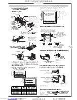
Page 87: ...ige Hälterung zum Stütze Installieren an einer Holzstruktur Ein Holzstück mit geeigneter Größe über zwei Balken legen und die Hängeschrauben an diesem Holzstück anbringen Installieren an einem Stahlrahmen Die rechtwinklige Halterung in der Struktur verwenden bzw eine Halterung zum Stützen verwenden Installieren an einer vorhandenen Betonplatte Inlochanker stöpsel oder schrauben für die Installieru...

Page 88: ...B 464BH B 1050 1350 2 164BH B 400 700 Wahlzubehör l Als Zubehör lieferbar ist ein TOSHIBA Filterbausataz für langfristigen Gebrauch l Der Filterbausataz kan entweder am unteren oder hinteren Lufteinlauf der Dukteinheit eingebaut werden RAV 164BH B Versorgungsflansch RAV 264BH B RAV 364BH B RAV 464BH B Rückleitungsflansch RAV 164BH B RAV 264BH B RAV 364BH B RAV 464BH B Schutzplatte Löcher mit ø 6 l...

Page 89: ...llationsposition und Auszugsrichtung der Rohre und Verdrahtung RÜCKWÄRTIGE ANSICHT Ausbrechöffnung rückwärtige Anbringung Gaszufüranschluß Ausbrechöffnung rechte oder linke Anbringung Ablaßanschluß OD 20mm Ausbrechöffnung obere Anbringung DRAUFSICHT Offnen der ausbrechbaren Offnung Den perforierten Teil mit einer Säge oder einem Messer aufschneiden Bei linken und rechten Rohren rechte oder linke A...

Page 90: ...naufhängung kann die Höhe des Innengeräts nach dem Aufhängen nicht mehr angepaßt werden dies muß jetzt geschehen 3 Aufhängung des Innengeräts Schlitzrillen Sechskantschraube Sechskantschrauben des Geräts in die Schlitzrillen einpassen 4 Sechskantschrauben zum Aufhängen des Geräts anziehen Fernbedienungskabel Nur Modelle CH C l Kabel über Kühlröhren und Ablaßröhren verlegen l Bei Verlegung unter de...

Page 91: ...e erforderlichen Schrauben in Pfeiler und Pfosten ein schrauben Damit die Innenanlage nicht nach vorne fällt zu diesem Zeitpunkt dafür sorgen daß die Anlage gut befestigt wird Dazu die Schrauben in den Löchern an beiden Enden der Einbauprofil anziehen Diese Löcher werden durch Schräglinien auf der Schablone angezeigt Löcher durch Schräglinien auf Schablone angezeigt Breitere Seite 4 Die Führungslö...

Page 92: ...bindungsflansch für den Leitungsanschluß vor Ort entsprechend der Abbildung vor RAV 104NH PE RAV 134 164 264NH PE Anschluss von Rohrung Gehäuse Luftauslaßgitter Beschaffung vor Ort Zufuhrleitung Beschaffung vor Ort Rohrverbindungsplatte Einheit Luftschachtauslaß Das Raumgerät besitzt zwei Austrittöffnungen für die Auslaßluft senkrecht abzugeben Die Innenanlage ist bereits in Richtung des vertikale...

Page 93: ...terung zum Stützen verwenden Querholzstück Hängeschraube Balken Decke Installieren an einer Holzstruktur Ein Holzstück mit geeigneter Größe über zwei Balken legen und die Hängeschrauben an diesem Holzstück anbringen Installieren an einer vorhandenen Betonplatte Inlochanker stöpsel oder schrauben für die Installierung verwenden Verstärkungsstange Installieren der Hängeschrauben Installieren an eine...

Page 94: ...Hängeschrauben ist auf dem Karton aufgedrückt Die Größe dagegen nicht Bmm Innere Aufhängung Den perforierten Teil mit einer Säge oder einem Messer aufschneiden Perforationsschlitz Bei linken und rechten Rohren rechte oder linke Anbringung Offnen der ausbrechbaren Offnung l Die Strichlinie zeigt das rückwärtige Ende der Einheit an An der Strichlinie abnehmen RÜCKWÄRTIGE ANSICHT Ablaßanschluß OD 20 ...

Page 95: ...ngung des Innengeräts Sechskantschraube Aufhänger 4 Sechskantschrauben zum Aufhängen des Geräts anziehen Fernbedienungskabel Nur SH Modell l Kabel über Kühlröhren und Ablaßröhren verlegen l Bei Verlegung unter den Röhren wäre es schwierig den Luftfilter herauszuziehen Wandschraube Max zulässiger Uberstand is 40 mm Aufhänger 40 mm oder weniger Heronhill for all your Toshiba requirements Tel 01823 6...

Page 96: ...legscheibe Installieren an einem Stahlrahmen Die rechtwinklige Halterung in der Struktur verwenden bzw eine Halterung zum Stützen verwenden Installieren an einer vorhandenen Betonplatte Inlochanker stöpsel oder schrauben für die Installierung verwenden 1 Sicherstellen daß der Abstand zwischen dem Boden des Innengeräts und der Unterseite der Decke 3mm beträgt vier Ecken 2 Sicherstellen daß der Abst...

Page 97: ...re Ablaßröhre Anschlußverdrahtung zwischen Innen und Außengerät sowie das Fernbedienungskabel an den Verrohrungs und Verdrahtungsanschlußpositionen vorbereiten bevor das Innengerät aufgehängt wird Rechtwinklige Hälterung zum Stütze Installieren an einem Stahlrahmen Die rechtwinklige Halterung in der Struktur verwenden bzw eine Halterung zum Stützen verwenden Querholzstück Hängeschraube Balken Deck...

Page 98: ...lierwaage Fest anziehen l Korrigieren Sie die Position und Höhe der Innenanlage in Relation zur Deckenöffnung unter Verwendung der Installationslehre die in der Schablone enthalten ist Ein Diagramm zur Verwendung der Teile ist auf der Installationslehre enthalten 1 Stellen Sie sicher daß der Abstand zwischen der Unterseite der Innenanlage und der Decke an allen 4 Ecken 43 mm beträgt 2 Stellen Sie ...

Page 99: ...3 Metallstege durchtrennen und dann das D förmige Metallstück mitsamt Wärmeisolierung herausnehmen Metall Frischlufteinlaß l Die Innenanlagen besitzen eine Ausstoßöffnung im Gehäuse durch die die Außenluft ins Innere der Anlage gelangt l Vor der Installation der Anlage an der Decke den Isolierblock mit der Ausstoßöffnung abnehmen und ein kurzes Rohrstück anbringen 6 Wärmeisolierung um das Rohr anb...

Page 100: ...sser nicht weiter als 30 mm hineingeschoben wird Wärmeisolierung 4 Kurzes Rohr an der Seite der Innenanlage anbringen und mit 6 Schrauben wie unten dargestellt befestigen Luftauslaßrohr Ø 150 Luftauslaß Die Ausstoßöffnung 1 Bei der Ausstoßöffnung handelt es sich um eine halbausgeschnittene rechteckige Öffnung an zwei Seiten der Anlage 3 Die 4 Metallstege durchtrennen und dann das rechteckige Metal...

Page 101: ...mung zu vermeiden Zudem wird eine Erhöhung des Gefälles empfohlen Wenn ein Ablaufsystem für mehrere Innenanlagen verwen det wird dann sind die Rohrleitungen wie nachfolgend abgebildet zu installieren 15 20m Stützklammer Isolierung Abwärtsgefälle 1 oder mehr Diesen Abstand so lang wie möglich machen ca 10 cm Abwärtsgefälle 30 Durchm Innendurchm 1 oder mehr Aufwärtsbiegung Abwärtsbiegung Rohrmateria...

Page 102: ... Fernbedienung betätigen Dadurch wird sichergestellt daß die Auslaßluftklappen in der korrekten Position sind Verdrahtete Fernbedienung l Zur Durchführung eines Kühlprobebetriebs den Betriebsartenwahlschalter auf die COOL Position stellen l Zur Einleitung des Kühlprobebetriebs die Taste ON OFF gedrückt halten Es werden Temperatur L und Gebläsedrehzahl AUTO angezeigt l Zur Einleitung des Heizprobeb...

Page 103: ...64AH AH8 A A8 364AH8 A8 464AH8 A8 Maximale Rohrleitungslänge vom Außengerät zum Innengerät Der maximale Höhenunterschied von der Außen zur Innenanlage Wenn das Außengerät darüber steht Wenn das Außengerät darunter steht 30 m 30 m 15 m 50 m 50 m 20 m Die Gesamtzahl der Biegungen im Rohrwerk sollte auf 10 oder weniger beschränkt werden Bei der Installation der Rohrleitungen sind folgende Punkte zu b...

Page 104: ...gen entnehmen Sie der Tabelle unten Ist in die Außeneinheit zuviel oder zuwenig Kältemittel eingefüllt worden tritt beim Kompressor einer Betriebsstörung auf Die vorgeschriebene Menge für die Kältemittelnachfüllung ist in der Tabelle unten angegeben FÜLLEN SIE BEI DIESEN ANLAGEN NUR R407C KÄLTEMITTEL EIN Wärmeisolierung Die Kältemittelrohrleitung jeweils auf der Flüssigkeitsseite und auf der Gasse...

Page 105: ...versorgung darf nur von einem qualifizierten Elektroingenieur oder techniker ausgeführt werden Darauf achten daß die für die Stromversorgung und für die Verdrahtung zwischen den Geräten verwendeten Kabel nicht mit Ventilen oder Röhren in Kontakt kommen die nicht mit Isolierstoffen umgeben sind Befestigen Sie diese Kabel an den Rohrabschnitten die mit Wärmeisolierung versehen sind Setzen Sie in die...

Page 106: ...er gesamten Gruppe von derselben Phase abgeleitet werden Keine Teile mit Ausnahme der Kabel sind fur die Gruppensteuerung erforderlich Die Stromkabel und Drahleitungsanschlüsse zwischen den Innen und Außengeräten auf die gle iche Weise wie die Anschlüsse für den Betrieb nur einer Klimaanlage herstellen Das Fernbedienungsgerät und die Innengeräte in der folgenden Reihenfolge anschließen 1 An die Kl...

Page 107: ...n gehen wenn der Netzschalter auf OFF AUS gestellt wird oder der Strom ausfällt Einzelheiten zur Einstellung der Fernbedienung entnehmen Sie der Bedienungsanleitung der Fernbedienung Befestigung auf der Wandoberfläche In der Mitte der oberen Kante des Zierdeckels eine U förmiger Ausschnitt machen und die runde 3 Leiter Polyvinylschlauchleitung durch den Ausschnitt verlegen Batterien zusammen mit d...

Page 108: ...cher verloren geht Einzelheiten zum Einstellen des Timers entnehmen Sie dem Benutzerhandbuch Installation der AI Fernbedienung Vorsichtsmaßnahmen FERNBEDIENUNGEN Aufputz Montage l Bringen Sie die Fernbedienung mit Hilfe zweier geeigneter Befestigungsschrauben nicht im Lieferumfang enthalten an der Wand an l Verbinden Sie das 3 adrige Kabel nicht im Lieferumfang enthalten mit den Anschlüssen A B un...

Page 109: ...ung herausnehmen Montage der Infrarot Fernbedienung Veinstellung des Luftstroms Zur Verbesserung der Kühl und Heizleistung stellen Sie die Auslaßluftklappe entsprechend für den Kühl bzw Heizbetrieb ein Die beste Auslaßluftklappenposition im Kühlbetrieb ist horizontal im Heizbetrieb vertikal Das Modell SH unterscheidet sich aufgrund seiner Installationsposition in diesem Fall sind die obi gen Klapp...

Page 110: ...verbinden 1 Anschluss A B und C der Fernbedienung mit Anschluss A B und C von Innenanlage 1 verbinden Dabei darauf achten die Anschlüsse nicht zu vertauschen 2 Anschluss B und C von Innenanlage 1 mit Anschluss B und C von Innenanlage 2 verbinden l CN12 Anschluß von Anlage 2 trennen jedoch an Anlage 1 angeschlossen lassen l Drehschalter SW01 auf 1 stellen für Innenanlage 1 auf 2 für Innenanlage 2 l...

Page 111: ...sigkeit Zweigrohrleitungen T Stück zu Innenanlage Ø19 1 3 4 Ø19 1 3 4 Ø15 9 5 8 Ø15 9 5 8 Ø12 7 1 2 Ø9 5 3 8 Ø6 4 1 4 Ø6 4 1 4 Ø6 4 1 4 Ø6 4 1 4 Ø15 9 5 8 Ø12 7 1 2 Ø12 7 1 2 Ø12 7 1 2 Ø12 7 1 2 Ø9 5 3 8 Ø9 5 3 8 Ø9 5 3 8 Ø9 5 3 8 Ø6 4 1 4 RAV 464AH8 PE RAV 364AH8 PE RAV 264AH8 PE RAV 264AH PE RAV 164AH PE Außenanlage Rohrleitungslänge eines Rohrs max Rohr leitungslänge L1 L2 L3 Höhenunterschied A...

Page 112: ...1 2 und 3 des Parallelinstallations Kits mit den Anschlüssen 1 2 und 3 der beiden Innenanlagen verbinden l Fernbedienung und Innenanlage in der folgenden Reihenfolge miteinander verbinden 1 Anschluss A B und C der Fernbedienung mit Anschluss A B und C von Innenanlage 1 verbinden Dabei darauf achten die Anschlüsse nicht zu vertauschen 2 Anschluss B und C von Innenanlage 1 mit Anschluss B und C von ...

Page 113: ...TA Sensors der Innenanlage 2 mit den mitgelieferten Kabelverbindungen bei der Spitze des TA Sensors der Innenanlage 1 Stift an so dass sich beide Sensorspitzen im Luftstrom befinden l Verbinden Sie den Stecker am Ende des vom Störschutzfilter kommenden 12 m Verlängerungskabels mit der Buchse des TA Sensors der Innenanlage 2 Überschüssige Kabellänge ist sicher aufzurollen 0 5 m Verlängerungskabel P...

Page 114: ...T Stück 264 164 134 134 Gas Flüssigkeit Gas Flüssigkeit Zweigrohrleitungen T Stück zu Innenanlage Ø19 1 3 4 Ø19 1 3 4 Ø15 9 5 8 Ø15 9 5 8 Ø9 5 3 8 Ø6 4 1 4 Ø6 4 1 4 Ø6 4 1 4 Ø15 9 5 8 Ø12 7 1 2 Ø12 7 1 2 Ø12 7 1 2 Ø9 5 3 8 Ø9 5 3 8 Ø9 5 3 8 Ø9 5 3 8 Bei einer max Rohrleitungslänge über 30 m sind Ø22 7 8 Rohre zu verwenden Rohrleitungen Max Rohrleitungslänge Dies ist die Summe der Hauptrohrleitung ...

Page 115: ... den unwahrscheinlichen Fall eines Lecks Wenn die sich hier bei ergebenden Dichte den Standardwert überschreitet dann muß entweder ein Entlüftungs oder ein Alarmsystem oder beides installiert werden Hierbei sind örtliche nationale und internationale Normen Vorschriften und Bestimmungen zu berücksichtigen WARTUNG DER KLIMAANLAGE Um die Möglichkeit einer Beschädigung der Klimaanlage möglichst auszus...

Page 116: ... sido concebidos para utilizarse en entornos comerciales e industriales CONDICIONES DE TRABAJO LISTA DE LOS MODELOS En este folleto se hace referencia a distintos tipos de unidad de interior indicando los códigos de modelo Los detalles se muestran en la tabla de abajo CÓDIGO BOMBA DE CALOR TIPO DE CONDUCTO INCORPORADO BH SBH B TIPO DE TECHO CH CHR C TIPO PARED KH KHR K TIPO CARCASA DE SUELO NH TIP...

Page 117: ...ciones Especificaciones de Fuente de Alimentación Cableado del Suministro Electrico 143 Cableado Entre los Equipos Conexión del Mando a Distancia Control de Grupos 144 Mando a Distancia Instalación de Controladores Remotos Bomba de Calor AI Instalación Electrica de 2 Mando a Distancia Modelos Refrigerantes 145 Instalación del mando a distancia de habitación de AI Mando a distancia de habitación de...

Page 118: ...NTIDAD DIAGRAMA APLICACIÓN Tornillos de ø 5 1 mm x 45 mm de largo 8 Para fijar la abrazadera de montaje Plantilla para la instalación de 1 Para poder señalar facilmente la la unidad de interior situación de la abrazadera de montaje Abrazadera de montaje 1 Para el montaje de la unidad de interior en la pared Esta pieza se sujeta temporalmente en la parte posterior de la unidad de interior DESCRIPCI...

Page 119: ...po de exteriores Donde el desagüe de agua pueda ocasionar molestias o presentar un peligro potencialmente peligroso si se helara Donde puedan soplar fuertes vientos contra la toma de entrada de aire del equipo de exteriores Podría dispararse el conmutador de alta presión si soplara un fuerte viento contra la salida de aire durante la operación de refrigeración Cuando pueda darse esta circunstancia...

Page 120: ...da de aire orientada a la pared Espacio para conexiones eléctrica y frigorífica 500 mm o más 300 mm o más A mm o más Salida de aire orientada a la pared No permita que las unidades se situen de manera que el aire de salida de una unidad entre directamente en la entrada de otra unidad de la manera indicada abajo Montaje Modelo A mm RAV 364AH8 A8 150 RAV 464AH8 A8 150 Modelos restantes 100 A mm o má...

Page 121: ...s 790 364 340 45 En áreas sometidas a fuertes nevadas proteja la unidad exterior contra la nieve como sigue i Instale la unidad sobre un soporte que la mantenga encima del nivel de la nieve caída ii El soporte tiene que permitir la salida de agua iii Instale caperuzas contra la nieve sobre las timas de entrada y salida de aire Cerciórese de que el flujo de aire no se vea afectado iv El no implemen...

Page 122: ...es Buena ubicación Refrigerado uniforme Mala ubicación Zona de línea oblicua no refrigerada debidamente Mala ubicación Zona de línea oblicua no refrigerada debidamente 7 7 3 Si no fuera posible encontrar una ubicación buena úsese un ventilador que distribuya el aire uniformemente en toda la dependencia Solo unidades UH U Escoja el número de flujos de aire que se requieren según la forma de la habi...

Page 123: ...30 mm o más 300 mm o más 150 mm o más 500 mm o más 400 mm o más 150 mm o más Proporcione un orificio de inspección aproximadamente aquí Orificio de inspección Unidades NH Mínimo Toma de salida de aire Lugar de fijación al suelo base Mínimo 150 mm 160 mm 20 mm 145 mmm 150 mm 100 mm 60 mm 25 mm Placa superior placa del conducto 140mm 65mm 90mm Depósito de drenaje Heronhill for all your Toshiba requi...

Page 124: ...mm o más 600 mm 600 mm 200 mm 600 mm Unidades UH U Units Techo 15 mm o más 1000 mm o más 1000 mm o más 150 mm o más 400 mm o más Obstáculo 1000 mm o más Caja terminal conexiónes de cables Tubo de descarga Salida de aire Caja de componentes eléctricos Placa de circuito impresa transformador condensador MF Heronhill for all your Toshiba requirements Tel 01823 665660 www heronhill co uk Fax 01823 665...

Page 125: ...era de tamaño apropiado a través de dos vigas e instale los pernos de colgar en este tramo de madera Instalación en un armazón de acero Utilice la abrazadera angular en la estructura o instale una para apoyo Instalación en una losa de hormigón existente Utilice anclajes de tarraja obturadores de tarraja o pernos de tarraja para la instalación Unidad de colgar 1 Levante la unidad utilizando un elev...

Page 126: ...64BH B 1050 1350 2 164BH B 400 700 Accessorio opcional l Existe un Equipo de Filtro de Larga Vida TOSHIBA como accesorio opcional l Puede instalarse el Equipo de Filtro tanto en la entrada de aire inferior como posterior de la unidad de Modelo Conducto l Para conectar el conducto cuadrado prepare la brida de conexión localmente como se indica a continuación RAV 164BH B Brida de impulsión RAV 264BH...

Page 127: ... la caja de cartón El tamaño no va impreso B mm colgado interior C mm colgado exterior Método de instalación del perno de colgar Losa de hormigón recién instalada Instale los pernos de colgar con los encastres pernos de cimentación etc Estancia Estructura de madera Coloque los pernos de colgar en un tramo cuadrado de madera situado sobre las vigas Viga Encastre con filo Encastre deslizante perno d...

Page 128: ...r después de instalada ajustarla en este momento 3 Instalación de la unidad interior Muescas de la hendidura Perno hexagonal Acople los pernos hexagonales de la unidad en las muescas de la hendidura 4 Apriete los pernos hexagonales para colgar la unidad Cable de control remoto Solo Modelos CH C l Haga un rizo con el cable por las tuberías de refrigeración y las tuberías de desagüe l Si se hace un ...

Page 129: ...as en los dispositivos de anclaje Sin embargo en los casos en que se usen tacos dilatables deberá ajustarse la profundidad de los agujeros de suerte que las cabezas de tuerca no sobresalgan más de 15 mm Precauciones Puede haber un cable eléctrico empotrado en la pared Examine los planos suministrados por el constructor Asegurarse de que la ménsula de instalación esté bien fijada antes de montar la...

Page 130: ... preparar la brida de conexión localmente tal y como se muestra RAV 104NH PE RAV 134 164 264NH PE Conexion de Conducto Entorno arquitectónico Rejilla de salida de aire abastecimiento local Conducto de suministro abastecimiento local Placa empalmadora de conducto Unidad Toma de Salida El aparato de interiores ofrece dos posibles tomas de salida de aire La unidad de interior ya estará posicionada en...

Page 131: ...no de cimentación Perno de cimentación par colgar los tubos Instalación de cuatro pernos de colgar de 10 de diámetro l Instale los pernos de colgar según los intervalos que se muestran en la figura superior l utilice pernos de colgar de 10 de diámetro obtenidos de comercios locales 131 E INSTALACIÓN DE UNIDADES DE INTERIOR Colgador Unidad de colgar 1 Levante la unidad utilizando un elevador y a co...

Page 132: ...m Corte la porción con la hendedura con una sierra o un cuchillo Ranura En caso de dispositivo a derecha o izquierda Para abrir el orificio del destapadero l La línea de puntos indica el extremo posterior de la unidad Separar por la línea de puntos VISTA POSTERIOR Conexión del drenaje OD 20 mm VISTA LATERAL Instalación de pernos de pared de diámetro 10 Los pernos de pared diámetro 10 obtenidos de ...

Page 133: ...ior Perno hexagonal Colgador Acople los pernos hexagonales de la unidad en las muescas de la hendidura 4 Apriete los pernos hexagonales para colgar la unidad Cable de control remoto Solo Modelo SH l Haga un rizo con el cable por las tuberías de refrigeración y las tuberías de desagüe l Si se hace un rizo con el cable bajo la tubería resultará más dificil sacar el filtro de aire Perno hexagonal Dej...

Page 134: ...tale los pernos de colgar en este tramo de madera Instalación en una losa de hormigón existente Utilice anclajes de tarraja obturadores de tarraja o pernos de tarraja para la instalación 1 Compruebe que la distancia entre la parte inferior de la unidad interior y el lado inferior del techo sea de 3 mm cuatro esquinas 2 Compruebe que la distancia entre el lado de la unidad interior y el techo sea d...

Page 135: ...nidad haya sido colgada Después de seleccionar la conexión de la tuberia Si el techo y está instalado posiciones conexión de tuberías y cableado de conexión antes de suspender la unidad interior Perno de colgador Abrazadera angular de apoyo Viga Techo Instalación en una estructura de madera Coloque un tramo de madera de tamaño apropiado a través de dos vigas e instale los pernos de colgar en este ...

Page 136: ...ntilla Se indica un diagrama para el uso de las piezas en el calibre de instalación 1 Asegúrese de que la distancia entre el fondo de la unidad de interior y la cara inferior del techo sea 43 mm en las 4 esquinas 2 Asegúrese de que la distancia entre el lado de la unidad de interior y el techo sea 30 mm por todos los lados Instalación de la Unidad Unidades UH U continúa Unidad de Colgar l Ajuste l...

Page 137: ...ico de la unidad de interior Parte metálica Entrada de aire fresco 6 Añada el aislante térmico alrededor de la guía para eliminar la posibilidad de formación de condensación en las superficies metálicas Recipiente de drenaje Bloque de aislamiento 4 Extraiga el bloque de aislamiento situado en el recipiente de drenaje que está sobre la entrada de aire fresco 32 ø100 130 130 4 ø6 ø144 ø130 80 10 30 ...

Page 138: ...da una guía en el lado de la unidad de interior y colóquela utilizando los 6 agujeros de tornillo como se muestra debajo Guía para la salida de aire Ø 150 Conducto de salida de aire Detalles del corte incompleto 1 Es un agujero de medio corte de forma rectangular situado en dos lados de la unidad 3 Corte las 4 lengüetas para extraer la parte rectangular metálica y el aislante térmico de la unidad ...

Page 139: ...ontaje en la parte inferior l Sujete la placa de fijación del tubo de drenaje con tornillos en la parte inferior del hueco de la pieza desmontable posterior inferior y sujete el tubo de drenaje con la cinta de nilón El nudo en la cinta de nilón debe quedar en el lado interior encima de la placa de montaje del tubo de drenaje Si se sujeta el tubo de drenaje sólo a la parte posterior inferior se deb...

Page 140: ...obación del contactor magnético Antes de realizar la puesta en marcha de prueba asegúrese de haber quitado todo el embalaje de la unidad y compruebe que estén abiertas las válvulas de servicio Se puede llevar a cabo una marcha de prueba forzada sea de refrigeración o calefacción sin tener en cuenta la temperatura ambiente Solo TUH TUH 1 TU TU 1 A la hora de poner la unidad en marcha por primera ve...

Page 141: ...odelo RAV 134AH A 164AH A 264AH AH8 A A8 364AH8 A8 464AH8 A8 La longitud máxima de tubería desde el equipo de exteriores al de interiores La máxima diferencia de altura entre la unidad de exterior y la de interior Si el equipo de exteriores está encima Si el equipo de exteriores está abajo 30 m 30 m 15 m 50 m 50 m 20 m Limite el número total de curvaturas en la tubería a 10 o menos A la hora de in...

Page 142: ... siguiente al medir la presión durante el funcionamiento Se requiere una galga ya que se usan juntas de verificación para empalmar las secciones Lado alta presión Lado baja presión Durante refrigeración Junta verificación unidad exterior Válvula empaquetada lado gas Durante calefacción Válvula empaquetada lado gas Junta verificación unidad exterior Nota Durante las operaciones de refrigeración la ...

Page 143: ...a mordaza de cable La conexión de alimentación debe ser realizado exclusivamente por un ingeniero o técnico eléctrico cualificado No permita que los cables utilizados para fuente de alimentación y para conexion entre unidades entrien en contacto con válvulas o tuberías no cubiertas de aislantes Secure these cables to the parts of the pipes with heat insulation fitted Sujete estos cables a las part...

Page 144: ...sistema de grupo que todos los circuitos de control de todo el grupo se deriven de la misma fase No se requieren piezas salvo cables para el control de grupos Realice las conexiones de cables de corriente y conexiones entre las unidades interiores y exteriores del mismo modo exactamente que para el funcionamiento como acondicionadores de aire individuales Conecte el controlador remoto y las unidad...

Page 145: ...lles sobre la regulación del mando a distancia consulte las instrucciones de manejo en el manual del usuario del mando a distancia Montaje en superficie de pared Haga un corte en forma de U en el centro del borde superior de la tapa decorativa y pase el cable cabtyre redondo de PVC de tres conductores a través del corte Instalación eléctrica de 2 mandos a distancia l Con el sistema AI se puede con...

Page 146: ... sección indicada por una flecha El condensador de la memoria previene la pérdida de memoria en caso de una interrupción de la corriente Para detalles sobre cómo poner el mando a distancia refiérase a las instrucciones en el manual de instrucciones del mando MANDO A DISTANCIA Montaje en la superficie del muro l Sujete el mando a distancia al muro con dos pernos de montaje apropiados obténganse loc...

Page 147: ...O Posición 1 APAGADO Posición 1 APAGADO Posiciones 1 y 2 Posición 2 APAGADO Posición 2 ENCENDIDO Posición 2 APAGADO Temperatura aumentada Prefijada en fábrica 2 C 4 C MANDO A DISTANCIA Localización del mando a distancia infrarrojo Posicion en la que Emplazar el Mando de Control Remoto per Rayos Infrarroyos Mantenga el mando de control remoto en una posición tal que sus emisiones lleguen al recepto...

Page 148: ...B y C en el mando a distancia y la unidad de interior No 1 asegurándose de que los terminales están conectados correctamente 2 Conecte entre sí los terminales B y C en las unidades de interior No 1 y No 2 l Quite el conector CN12 de la unidad de interior No 2 pero déjela conectada en la unidad de interior No 1 l Ponga el interruptor rotatorio SW01 en 1 para la unidad de interior No 1 y 2 para la u...

Page 149: ... interiror Ø19 1 3 4 Ø19 1 3 4 Ø15 9 5 8 Ø15 9 5 8 Ø12 7 1 2 Ø9 5 3 8 Ø6 4 1 4 Ø6 4 1 4 Ø6 4 1 4 Ø6 4 1 4 Ø15 9 5 8 Ø12 7 1 2 Ø12 7 1 2 Ø12 7 1 2 Ø12 7 1 2 Ø9 5 3 8 Ø9 5 3 8 Ø9 5 3 8 Ø9 5 3 8 Ø6 4 1 4 RAV 464AH8 PE RAV 364AH8 PE RAV 264AH8 PE RAV 264AH PE RAV 164AH PE Unidad de exterior Longitud de un tubo Longitud máxima de los tubos L1 L2 L3 Diferencia de altura De la unidad de exterior a la uni...

Page 150: ... unidades de interior l Conecte el mando a distancia y la unidad de interior del siguiente modo 1 Conecte entre sí los terminales A B y C en el mando a distancia y en la unidad de interior No 1 asegurándose de que los terminales están conectados correctamente 2 Conecte entre sí los terminales B y C en las unidades de interior No 1 y No 2 l Quite el conector CN12 de la unidad de interior No 2 pero ...

Page 151: ...tuados en el flujo de aire l Conecte el enchufe macho en el extremo del cable de extensión de 12m desde el filtrador de ruido al enchufe hembra del sensor TA en su posición nueva asegurándose de que la parte sobrante de cable está enrollada Cable de extensión de 0 5m artículo 3 Unidad de interior 1 Sensor TA de la unidad 2 en la posición nueva Sensor TA de la unidad 1 Cable de extensión de 12m art...

Page 152: ... que se puede imponer en un sistema y toma en cuenta los accesorios de tuberías y las curvas Refrigerante adicional se necesita únicamente si la longitud máxima de la tubería L1 L2 L3 excede los 20m vea la página 142 con el título Refrigerante complementario para más detalles Unidad de exterior Longitud de un tubo Longitud máxima de los tubos L1 L2 L3 Diferencia de altura De la unidad de exterior ...

Page 153: ...aso más desfavorable usando la carga total del refrigerante en el caso improbable de producirse una fuga Si el nivel de la densidad resulta superior a la norma se debe instalar entonces un sistema de ventilación o un sistema de alarma o ambos Se debe completar el proceso arriba indicado según las normas códigos de práctica y requisitos estatutarios locales nacionales e internacionales MANTENIMIENT...

Page 154: ...ulla Bassa Tensione e 89 336 CEE Direttiva sulla Compatibilità Elettromagnetica Di conseguenza esse sono designate all impiego in ambienti commerciali ed industriali CONDIZIONI DI ESERCIZIO ELENCO DEI MODELLI Il presente manuale fa riferimento a vari tipi di unità per interni in base al codice del modello Per i dettagli vedi la tabella che segue DESCRIZIONE UNITÀ CODICE POMPA DI CALORE CODICE SOLO...

Page 155: ...gamenti fra le Unità Collegamento del Telecomando Controllo Gruppo 182 Telecomando Installazione di due Comandi Remoti Modelli con Pompa di Calore AI Cablaggio di 2 Telecomandi Modelli solo Raffreddamento 183 Installazione del Telecomando per ambienti AI Telecomando per ambienti AI per modelli a pompa di calore 184 Ubicazione del Telecomando a IR Installazione del Telecomando agli Infrarossi Monta...

Page 156: ...CHEMA APPLICAZIONE Viti diam 5 1 mm x 45 mm 8 Per il fissaggio della staffa di installazione Sagoma per l installazione 1 Per agevolare la marcatura della posizione dell unità per interni staffa di installazione Staffa di installazione 1 Per il montaggio a muro dell unità per interni questa parte si trova temporaneamente fissata alla parte posteriore dell unità per interni DESCRIZIONE QTÀ SCHEMA A...

Page 157: ...re appieno il peso dell unità per esterni Ove il drenaggio dell acqua potrebbe causare disturbo o costituire un pericolo in presenza di gelo In presenza di forti raffiche di vento contro la presa dell aria sull unità per esterni L interruttore d alta pressione potrebbe scattare se un forte vento soffia contro l uscita d aria durante l operazione di raffreddamento In questo caso proteggere l unità ...

Page 158: ... aria rivolta verso il muro Spazio per la tubazione e il cablaggio 500 mm o più 300 mm o più Presa d aria rivolta verso il muro Non permettere il posizionamento delle unità in modo che l aria in uscita da un unità possa essere scaricata direttamente nell ammissione di un altra unità come indicato sotto Montaggio Modello A mm RAV 364AH8 A8 150 RAV 464AH8 A8 150 Altri modelli 100 A mm o più Spazio p...

Page 159: ...tri modelli 790 364 340 45 Nei luoghi dove nevica molto proteggere l unità esterna dalla neve nel modo seguente i Installare l unità su un supporto che la mantenga al di sopra del livello dell altezza neve ii Il sostegno usato deve facilitare il drenaggio dell acqua iii Installare cappucci anti neve sulla presa e sullo sbocco dell aria Controllare che il flusso dell aria non risulti ostruito Se no...

Page 160: ... dell aria fredda Collocazione Precauzioni Posizione adatta Raffreddamento uniforme Posizione non adatta La zona tratteggiata non è ben raffreddata Posizione non adatta La zona tratteggiata non è ben raffreddata 7 7 3 Se non fosse possibile trovare la posizione adatta fare circolare l aria uniformemente nel locale per mezzo di un ventilatore Soltanto Unità UH U Scegliere il numero di flussi d aria...

Page 161: ...00 mm o più 400 mm o più 150 mm o più Praticare un foro d ispezione qui intorno Foro d ispezione 300 mm o più 300 mm o più 30 mm o più Unità NH Piastra superiore piastra condotto Posizione di fissaggio a pavimento base Minimo Minimo 150 mm 90 mm 160 mm 20 mm 145 mm 150 mm 100 mm 60 mm 25 mm Sbocco dell Aria 140mm 65mm Raccoglitore di scolo Heronhill for all your Toshiba requirements Tel 01823 6656...

Page 162: ...mm o più 150 mm o più 400 mm o più Ostacolo 1000 mm o più 500 mm o più 150 mm o più Pianta 150 mm o più 600 mm 600 mm 1000 mm o più 200 mm Cassetta di terminazione Connessioni dei fili Tubo di scarico Scatola dei componenti elettrici PCB Trasformatore Condensatore MF Uscita dell aria Heronhill for all your Toshiba requirements Tel 01823 665660 www heronhill co uk Fax 01823 665807 ...

Page 163: ...azione su telaio d acciaio Usare la staffa angolare della struttura o installarne una di supporto Installazione su cemento già esistente Per l installazione usare ancoraggi viti o bulloni perforanti Unità da sospendere 1 Sollevare l unità con un attrezzo adatto e mettere i supporti pendenti sui bulloni di sospensione Fissare i dadi su entrambi i lati superiore e inferiore del supporto pendente e l...

Page 164: ...HIBA di filtro a lunga durata è disponibile come accessorio a scelta l Il kit filtro può essere montato sia all ingresso area inferiore che a quello posteriore dell unità a condotto l Per collegare il condotto quadrato preparare local mente la flangia di connessione come mostrato sotto RAV 164BH B Flange di mandata RAV 264BH B RAV 364BH B RAV 464BH B Flange di ritorno RAV 164BH B RAV 264BH B RAV 3...

Page 165: ... sospensione delle tubature Barra di rinforzo Bullone per fondazione Installazione dei bulloni esagonali accessori Lasciare uno spazio di circa 10 mm Bulloni esagonali M8 x 25 mm 4 Determinazione della posizione di installazione e direzione del cablaggio e delle tubature VEDUTA POSTERIORE Foro incompleto collegamento di destra o sinistra Collegamento di scarico OD 20 mm VEDUTA SUPERIORE Apertura d...

Page 166: ... Muro In caso di sporgenza interna dopo la sospensione non è più possibile regolare l altezza dell unità interna regolarlo adesso 3 Sospensione dell unità interna Fori di scivolamento Bullone esagonale Montare i bulloni esagonali dell unità nei fori di scivolamento 4 Serrare i bulloni esagonali per sospendere l unità Lasciare una lunghezza di 40mm o memo Filo del comando a distanza Soltanto per i ...

Page 167: ...a per garantire che la testa del bullone sporga di non più di 15 mm Precauzioni Potrebbero esserci tubi protettivi nella parete Verificare le piante dell imprenditore edile Prima di procedere al montaggio dell unità interna verificare che la mensola di montaggio sia sicuramente montata Tassello di ancoraggio Base di montaggio Ancoraggio espandibile Tubo sul retro l Utilizzando il modello trovare l...

Page 168: ...rso l alto come mostrato dalla freccia ed estrarla dall unità Viti di fissaggio 2 Scatola dei componenti elettrici Per il collegamento con il condotto preparare localmento la flangia di connessione nel modo illustrato RAV 104NH PE RAV 134 164 264NH PE Collegamento dei condotti Involucro architettonico Griglia di uscita per l aria da acquistare in zona Condotto di alimentazione da acquistare in zon...

Page 169: ...dotto di alimentazione da procurarsi localmente Condotto di ritorno da procurarsi localmente Pannello di copertura montato in fabbrica Unità da sospendere 1 Sollevare l unità con un attrezzo adatto e mettere i supporti pendenti sui bulloni di sospensione Fissare i dadi su entrambi i lati superiore e inferiore del supporto pendente e le rondelle lato inferiore soltanto 2 Installare l unità orrizont...

Page 170: ...ulloni di ancoraggio sono stampate sulla scatola di cartone La misura non è stampata B mm sospensione interna Tagliare la parte per il lungo con una sega o un taglierino Apertura del foro incompleto l La linea tratteggiata indica l estremità posteriore dell unità Staccare lungo la linea tratteggiata VEDUTA POSTERIORE Collegamento di scarico OD 20 mm Foro incompleto collegamento di destra o di sini...

Page 171: ...one esagonale Staffa Montare i bulloni esagonali dell unità nelle staffe 4 Serrare i bulloni esagonali per sospendere l unità Filo del comando a distanza Soltanto per i modelli SH l Fissare il filo sul tubo di raffreddamento e sul tubo di scarico l Se i fili erano collegati sotto i tubi potrà essere difficoltoso estrarre il filtro dell aria Bullone esagonale Lasciare una lunghezza di sporgenza di ...

Page 172: ...no di lunghezza appropriata fra due travi e installare su di essa i bulloni di sospensione Unità di sospensione l Regolare le posizioni dei dadi lato inferiore in modo che la distanza tra la rondella lato inferiore e il soffitto sia di 140 mm l Sospendere il dado del bullone di sospensione alla scanalatura a forma di U nel corpo della macchina l Controllare il livello del corpo usando una livella ...

Page 173: ...o per mantenere il soffitto perfettamente orizzontale ed evitare che vibri la struttura deve essere rinforzata 2 Ritagliare e rimuovere parte della placca del soffitto 3 Rinforzare le estremità della struttura del soffitto dove è stato tagliato l Alcune connessioni delle tubazioni e del cablaggio vanno fatte sul soffitto dopo la sospensione dell unità Dopo aver scelto la posizione d installazione ...

Page 174: ... pompa di scarico e un interruttore a galleggiante il corpo deve essere orizzontale Se il corpo viene installato in posizione inclinata l interruttore a galleggiante non funziona correttamente e causa perdite d acqua l Stringere il dado superiore e fissare la posizione dell unità Livella Staffa Soffitto Unità interna Maschera Staffa Dado Dado Rondella Staffa Rondella Installazione dell unità Unità...

Page 175: ...co dall unità interna Metallo Entrata dell aria fresca l Questi modelli dispongono di un foro incompleto che consente all aria esterna di entrare nell unità interna l Prima di installare l unità aprire il foro incompleto e il blocco isolante e montare una chiave d inserzione per collegare il tubo prima di montare a parete l unità 6 Aggiungere dell isolante termico attorno alla chiave d inserimento...

Page 176: ...piastrina metallica rettangolare e l isolante termico dall unità interna Metallo 6 ø6 ø 180 45 45 ø150 6 80 10 30 ø200 4 5 ø 180 4 5 5 Aggiungere dell isolante termico attorno alla chiave d inserimento per evitare il rischio che si formi della condensa sulle superfici metalliche Condotto di uscita dell aria l Per ottimizzare la distribuzione dell aria negli ambienti si può dividere l uscita dell a...

Page 177: ...ficientemente sostenuto al fine di evitare distorsioni Si consiglia eventualmente anche di incrementare il gradiente Nel caso in cui si utilizzi un solo impianto di scarico per più unità interne installare la tubazione come indicato sotto 150 200 mm Supporto di fissaggio Isolamento Gradiente a scendere 1 100 o maggiore Rendere l intervallo quanto più lungo possibile circa 10 cm Gradiente a scender...

Page 178: ...te test del magnetotermico Prima di condurre la marcia di prova assicurarsi di aver rimosso tutti gli imballaggi dall unità e controllare che le valvole di servizio siano aperte È possibile forzare la marcia di prova sia in modalità raffreddamento che riscaldamento indipendentemente dalla temperatura ambiente Soltanto per TUH TUH 1 TU TU 1 Quando si pone in esercizio l unità per la prima volta pre...

Page 179: ... 2 mm 7 8 Possibile Lunghezza e Salto dei Condotti Modello RAV 134AH A 164AH A 264AH AH8 A A8 364AH8 A8 464AH8 A8 Lunghezza massima condotti da unità per esterni a unità per interni Differenza di quota massima fra unità esterna e unità interna Con l unità per esterni sopra Con l unità per esterni sotto 30 m 30 m 15 m 50 m 50 m 20 m Limitare il numero complessivo di gomiti presenti nella tubazione ...

Page 180: ...nzionamento È richiesto l uso di un indicatore misuratore di controllo in quanto il collegamento fra le sezioni si ottiene per mezzo di giunti di ritenuta Lato alta pressione Lato bassa pressione Durante il raffreddamento Controllare il giunto nell unità esterna Valvola a pacco lato gas Durante il riscaldamento Valvola a pacco lato gas Controllare il giunto nell unità esterna Nota Durante l operaz...

Page 181: ...ento elettrico deve essere eseguito soltanto da un tecnico qualificato Fare attenzione che i cavi usati per l alimentazione della corrente e per il collegamento tra le unità non vengano a contatto con le vavole e le tubazioni non coperte con isolante Assicurare i citati cavi alle parti del tubo dotato di isolamento termico Usare i fori incompleti da Ø 20 mm forniti con l unità eccettuato KH KHR K ...

Page 182: ...istruzioni complete sul settaggio e l esercizio del controller in oggetto sono incluse nel manuale dell utente fornito con il telecomando Controllo Gruppo Soltanto per BH CH KH NH SBH SH TUH TUH 1 UH Usando un singolo comando a distanza si può controllare fino ad un gruppo di 16 condizionatori d aria circuito di controllo per ogni unità per interni ha origine in corrispondenza dell unità esterna a...

Page 183: ...dell ora memorizzata e altre impostazioni vadano perdute anche quando l interruttore generale è in posizione OFF o in caso di mancanza di alimentazione elettrica Per i particolari sull impostazione del Telecomando vedi le istruzioni di funzionamento di cui al Manuale Utente del Telecomando Montaggio in superficie su parete Praticare un intaglio a forma di U al centro del bordo superiore del coperc...

Page 184: ... Il condensatore della memoria di riserva evita perdite di memoria in caso di interruzione dell alimentazione elettrica Per informazioni sulla configurazione del telecomando consultare le istruzioni per l uso riportate nel manuale per l utente del telecomando TELECOMANDO Montaggio a parete l Fissare il telecomando alla parete usando due viti di fissaggio adatte acquistate sul posto l Collegare il ...

Page 185: ...ne di migliorare gli effetti del raffreddamento riscaldamento utilizzare adeguatamente le feritoie di ventilazione per tali operazioni In modalità raffreddamento la posizione più efficace delle feritoie è quella orizzontale mentre in modalità riscaldamento la posizione ottimale è quella verticale Il battente si differenzia in base alla posizione di installazione Se del caso invertire le posizioni ...

Page 186: ...omando e dell unità interna n 1 assicurandosi che i terminali vengano correttamente abbinati 2 Collegare tra loro i terminali B e C delle unità interne n 1 e n 2 l Togliere il connettore CN12 dall unità interna n 2 ma lasciarlo collegato sull unità interna n 1 l Regolare a 1 il selettore a rotazione SW01 dell unità interna n 1 e regolare a 2 quello dell unità interna n 2 l Regolare la posizione 1 ...

Page 187: ...9 1 3 4 Ø15 9 5 8 Ø15 9 5 8 Ø12 7 1 2 Ø9 5 3 8 Ø6 4 1 4 Ø6 4 1 4 Ø6 4 1 4 Ø6 4 1 4 Ø15 9 5 8 Ø12 7 1 2 Ø12 7 1 2 Ø12 7 1 2 Ø12 7 1 2 Ø9 5 3 8 Ø9 5 3 8 Ø9 5 3 8 Ø9 5 3 8 Ø6 4 1 4 RAV 464AH8 PE RAV 364AH8 PE RAV 264AH8 PE RAV 264AH PE RAV 164AH PE Unità esterna Lunghezza del tubo di un tubo Lunghezza massima del tubo L1 L2 L3 Differenza di altezza Dall unità esterna all unità interna Lunghezza del r...

Page 188: ...ntrambe le unità interne l Collegare il telecomando e l unità interna nel modo seguente 1 Collegare tra loro i terminali A B e C del telecomando e dell unità interna n 1 assicurandosi che i terminali vengano correttamente abbinati 2 Collegare tra loro i terminali B e C delle unità interne n 1 e n 2 l Togliere il connettore CN12 dall unità interna n 2 ma lasciarlo collegato sull unità interna n 1 l...

Page 189: ... interna n 1 sul montante di supporto per garantire che si trovino entrambi esposti al flusso d aria l Collegare la spina maschio all estremità della prolunga da 12m proveniente dal filtro rumore alla spina femmina del sensore TA riposizionato assicurandosi che la sezione eventualmente inutilizzata del cavo venga arrotolata in modo sicuro Prolunga da 0 5m Articolo 3 Sensore TA Unità n 2 Sensore TA...

Page 190: ...0 Unità esterna Tubi principali dall unità esterna al giunto a T 264 164 134 134 Gas Liquido Gas Liquido Tubi di raccordo dal giunto a T all unità interna Ø19 1 3 4 Ø19 1 3 4 Ø15 9 5 8 Ø15 9 5 8 Ø9 5 3 8 Ø6 4 1 4 Ø6 4 1 4 Ø6 4 1 4 Ø15 9 5 8 Ø12 7 1 2 Ø12 7 1 2 Ø12 7 1 2 Ø9 5 3 8 Ø9 5 3 8 Ø9 5 3 8 Ø9 5 3 8 Se la lunghezza massima del tubo supera i 30m va usato un tubo da Ø22 7 8 Dimensioni dei tubi...

Page 191: ...efrigerante nell improbabile caso in cui si verifichi una perdita Se il livello di densità risultante supera il livello standard installare un sistema di ventilazione o di allarme o entrambi Completare la procedura sopra descritta nel rispetto della normativa locale nazionale e internazionale della normale prassi e dei requisiti di legge MANUTENZIONE DEL PRODOTTO Per ridurre al minimo il rischio d...

Page 192: ...olg zijn zij bedoeld voor gebruik in commerciële en industriële omgevingen BEBRIJFSOMSTANDIGHEDEN CODE VOOR MODELNAMEN In dit boekje zullen voor verschillende types voor inpandig gebruik bestemde installaties modelcodes worden gebruikt Bijzonderheden worden getoond in de onderstaand tabel BUITENTEMPERATUUR 2 43 C KOELEN 10 21 C VERWARMEN KAMERTEMPERATUUR 18 32 C KOELEN 15 29 C VERWARMEN LUCHTVOCHT...

Page 193: ...Isolatie Drukmeting 218 Elektrische Bedrading Voorzorgsmaatregelen Voedingsspecificatie Bedrading van de Voeding 219 Bedrading Tussen Units Ansluiten van de Afstandsbediening Groepsbediening 220 Afstandsbedieningen Installatie van Afstandsbedieningen Warmtepompe AI modellen Bedrading van 2 Afstandsbedieningen Koeling Model 221 Montage van de AI Afstandsbediening Voorzorgsmaatregelen Warmtepomp Mod...

Page 194: ...et paneel vast te zetten op de cassette BESCHRIJVING AANTAL SCHEMA VORM TOEPASSING Zeskantige bout 4 Voor de bevestiging van de hangers Bevestigingsplaat van de 1 Voor het bevestigen van de achterzijde afloopleidingen van de afloopleidingen Isolatiebuis 2 Voor het isoleren van de pijpverbindingen Nylon riempje 10 Voor de bevestiging van de afloopleidingen en isolatie 2 Voor bevestiging van het zil...

Page 195: ...iten unit te dragen Waar de waterafvoer overlast kan veroorzaken of waar het gevaar kan opleveren als deze bevriest Waar krachtige windvlagen tegen de luchtinlaat van de buiten unit kunnen blazen De hogedruk schakelaar kan in werking treden als een sterke windvlaag tegen de luchtinlaat blaast tijdens koeling Als deze omstandigheid waarschijnlijk is de buiten unit beschermen tegen wird door bijvoor...

Page 196: ... bedrading en leidingen 500mm of meer 300mm of meer A mm of meer Luchtuitlaat naar de wand gericht Zorg ervoor dat de installaties niet zodanig worden geplaatst dat de uitlaatlucht van de ene installatie rechtstreeks wordt afgevoerd in de inlaat van een andere installatie zoals hieronder aangegeven Montage ROUTE VAN DE LUCHTSTROOM Model A mm RAV 364AH8 A8 150 RAV 464AH8 A8 150 Alle units 100 A mm ...

Page 197: ...440 416 45 Alle units 790 364 340 45 In gebieden met zware sneeuwval de buiten unit up de volgende manier tegen sneeuw beschermen i Installeer de installatie op een standaard die de installatie boven het niveau van de sneeuw op de grond zal houden ii De stallage moet waterafvoer gemakkelijk maken iii Monteeer sneeuw beschermkappen over de luchtinlaat en luchtuitlaat iv Zorg dat de luchtstroming he...

Page 198: ...tie Gelijkmatige koeling Slechte locatie Het schuin gearceerde gebied wordt niet goed gekoeld Slechte locatie Het schuin gearceerde gebied wordt niet goed gekoeld 7 7 3 Indien een juiste locatie niet mogelijk is gebruik dan een ventilator om de lucht door de gehele ruimte te laten circuleren ALLEEN UH U INSTALLATIES Kies het gewenste aantal luchtstromingen afhankelijk van de vorm van de ruimte en ...

Page 199: ...aties 300mm of meer 300mm of meer 150mm of meer 500mm of meer 400mm of meer 150mm of meer Zorg hier voor een inspectieluik Controlegaatje 30mm of meer NH Installaties Bovenste plaat Kanaalplaat 150mm 100mm Minimum Luchtuitlaat Montageplaats aan de bodem basis Minimum 150mm 160mm 20mm 60mm 145mm 25mm Afvoerreservoir 140mm 65mm 90mm Heronhill for all your Toshiba requirements Tel 01823 665660 www he...

Page 200: ... meer 150mm of meer 600mm 600mm 200mm 600mm UH U Installaties Plafond 15mm of meer 1000mm of meer 1000mm of meer 150mm of meer 400mm of meer Obstakel 1000mm of meer Aansluitdoos Aansluiting bekabeling Afvoerleiding Elektrische onderdelenkast Printplaat transformator MF condensator Luchtuitblaas Heronhill for all your Toshiba requirements Tel 01823 665660 www heronhill co uk Fax 01823 665807 ...

Page 201: ...f Funderingsbout Funderingsbout voor het ophangen van de leidingen Hoekbeugels voor steun Installatie op een houten constructie Plaats een stuk hout met de juiste afmetingen over twee balken en plaats de ophangbouten op dit stuk hout Installatie op een stalen frame Gebruik de hoekbeugel in de constructie of installeer er een voor steun Installatie op een bestaande betonnen plaat Gebruik ingats ank...

Page 202: ...0 1000 2 364BH B 464BH B 1050 1350 2 164BH B 400 700 Optionele accessoire l Een TOSHIBA filterset met lange levensduur is verkrijgbaar als optionele accessoire l De filterset kan zowel op de luchtinlaat aan de onder als de achterkant van de installatie van het kanaaltype worden geïnstalleerd l Bereid voor het aansluiten van een vierkant kanaal de aansluitflens ter plaatse op de hieronder getoonde ...

Page 203: ...mm Binnen ophanging Cmm uiten ophanging Montage van de ophangbout Pas aangebrachte betonplaat Monteer de ophangbouten met inzetstukken ingebedde bouten enz Hout vertrek met steunbalken Monteer de ophangbouten op een vierkant stuk hout dat over de balken is gelegd Stuk hout Balk Rand scherp inzetstuk Schuif inzetstuk Ingebedde bout van leidingen Verstevigingsstang bar Ingebedde bout Monteren van bo...

Page 204: ...ijk na het ophangen afstellen in dit stadium 3 Ophangen van de binnen unit Bevestigingssleuven Bout met zeskantige kop Monteer de bouten met zeskantige kop van de unit in de bevestigingssleuven 4 Draai de bouten met zeskantige kop vast om de unit op te hangen Snoer van de afstandsbediening Alleen CH C model l Het snoer boven de koelleidingen en de aflooppijpen leggen l Als het snoer onder de leidi...

Page 205: ... de beugel in het middel van een pilaar of stijl komt 3 Bij een houten wand is de afstand tussen de pilaren gewoonlijk 900 mm of 1 800 mm 2 700 mm en binnen deze lengte zijn stijlen geplaatst met afstanden van 300 tot 500 mm Zorg ervoor dat de beugel stevig wordt geplaatst door de bijbehorende schroeven in pilaren en stijlen te schroeven Zorg er nu voor om te voorkomen dat de inpandige installatie...

Page 206: ...it Bevestigingsschoeven x2 Elektrische kastje Voor aansluiting op het kanaal de aansluitflens ter plaatse maken zoals in de afbeelding RAV 104NH PE RAV 134 164 264NH PE Aansluiten van de kanalen Architectonische ombouw KANAALUITLAAT De binneneenheid heeft 2 luchtuitstroomstanden De binne neenheid zit al op zijn plaats in de verticale luchtuitlaa trichting wanneer een zij horizontale luchtuitlaatri...

Page 207: ... wordt gedaan kan er waterlekkage ontstaan Moer Sluitring Hangbout Ophangbout l Controleer de afmetingen van de installatie in de volgende afbeelding Installatie Van De Unit SBH Installaties Aansluiting van kanalen Luchtuitblaaskanaal bouwzijdig voorziening Luchtuitzuigkanaal bouwzijdig voorziening Afdekplaat fabriekszijdig aangebracht Plaatsen van Ø 10 ophangbouten 4 stks l Bevestig de draadeinde...

Page 208: ... aangegeven Bmm Binnen ophanging Het ingesneden deel met behulp van een zaag of mes verwijderen Openen van het uitbreekgat l De stippellijn geeft de achterzijde van de unit aan Losmaken op de stippellijn Achteraanzicht Aansluiting van de afloop buitendiameter 20 mm Uitbreekplaatje Voor bevestiging rechts of links ZIJAANZICHT Montage van ø 10 Muur bouten N B ø 10 Muur bouten ter plaatse aanschaffen...

Page 209: ...skantige kop van de unit in de bevestigingssleuven 4 Draai de bouten met zeskantige kop vast um de unit op te hangen Snoer van de afstandsbediening Allen SH modellen l Het snoer boven de koelleidingen en de aflooppijpen leggen l Als het snoer onder de leidingen zou worden gelegd zou dit problemen opleveren bij het uittrekken van het luchtfilter 40mm of minder Ophangbout Bout met zeskantige kop Hou...

Page 210: ...ie op een houten constructie Plaats een stuk hout met de juiste afmetingen over twee balken en plaats de ophangbouten op dit stuk hout Hangbout Ophangbout Hoekbeugels voor steun Installatie op een stalen frame Gebruik de hoekbeugel in de constructie of installeer er een voor steun Installatie op een bestaande betonnen plaat Gebruik ingats ankers ingats pluggen of ingats bouten voor de installatie ...

Page 211: ...het plafond al is geïnstalleerd bereid dan de koelmiddelleiding afvoerleiding verbindingsdraden van de inpandige naar de buiteninstallatie en het koord voor de afstandsbediening bij de leiding en bedradingsaansluitingsverbindingen voor alvorens de inpandige installatie op te hangen Installatie op een bestaande betonnen plaat Gebruik ingats ankers ingats pluggen of ingats bouten voor de installatie...

Page 212: ...er in de mal Op de installatiemeter bevindt zich een schema voor het gebruik van de onderdelen 1 Controleer of de afstand tussen de bodem van de inpandige installatie en de onderkant van het plafond in alle 4 de hoeken 43 mm is 2 Controleer of de ruimte tussen de zijkant van de inpandige installatie en het plafond overal 30 mm is Ophangbout Moer Sluitring Sluitring Ophangbout Moer Installatie Van ...

Page 213: ...m het metalen D vormige deel en de thermische isolator uit de binnenunit te halen Metaal Buitenluchtinlaat l Deze modellen hebben een uit te snijden opening in de kast waardoor buitenlucht in de binnenunit kan komen l Verwijder alvorens de unit te installeren de uit te snijden opening en het isolatieblok en plaats een insteekeind om de afvoerpijp aan te sluiten alvorens de unit op te hangen 6 Bren...

Page 214: ...ipjes door om het rechthoekige metalen deel en de thermische isolator te verwijderen van de binnenunit Metaal 6 ø6 ø 180 45 45 ø150 6 80 10 30 ø200 4 5 ø 180 4 5 l Om de luchtverdeling in een ruimte te verbeteren is het mogelijk de luchtuitlaat in de ruimte te splitsen Dit wordt bereikt door een distributiekanaal toe te voegen Per unit kan slechts één kanaal worden gebruikt l Verwijder alvorens de...

Page 215: ...teriaal Harde PVC leiding nominale diameter buiten Ø 20 mm Bevestiging van de Aftappan CH CHR C bevestiging aan de achterkant SH SHR bevestiging aan de onderkant l Schroef de bevestigingsplaat van de afvoerleiding op het onderste deel van de uitstoter aan de achter onderkant en bevestig de afvoerleiding met de nylonband De knoop in de nylonband moet aan de binnenkant zitten boven de bevestigingspl...

Page 216: ...t behulp van de magneetschakelaar proefknop Zorg ervoor alvorens proef te draaien dat al het verpakkingsmateriaal is verwijderd van de installatie en controleer of de servo afsluiters geopend zijn Er kan geforceerd worden proefgedraaid voor koeling of verwarming ongeacht de ruimtetemperatuur Alleen TUH TUH 1 TU TU 1 Druk wanneer de installatie voor het eerst wordt gebruikt op de JALOEZIEËN knop op...

Page 217: ... Model RAV 134AH A 164AH A 264AH AH8 A A8 364AH8 A8 464AH8 A8 De maximum leidinglengte van de buiten unit naar de binnen unit Het maximale hoogteverschil van de buiteninstallatie naar de inpandige installatie Als de buiten boven staat Als de buiten unit onder staat 30 m 30 m 15 m 50 m 50 m 20 m Beperk het totale aantal bochten in de leidingen tot 10 of minder Bij het installeren van leidingen is h...

Page 218: ...e drukmeter aan op de plaatsen in de onderstaande tabel tijdens het meten van de werkdruk Een meter is noodzakelijk daar er controleverbindingsstukken worden gebruikt voor het verbinden van deze delen Hogedruk kant Lagedruk kant Tijdens koeling Controleer de verbinding in de buiten unit Gaskant afdichtklep Tijdens verwarming Gaskant afdichklep Controleer de verbinding in de buiten unit Opmerking T...

Page 219: ...tten met een kabelklem De bedrading voor de voeding mag alleen worden aangelegd door een bevoegde elektromonteur of elektrotechnicus Zorg dat de kabels voor de voeding en voor de bedrading tussen de units niet in contact komen met kleppen of met leiding dei niet zijn afgedekt door isolatiemateriaal Zet deze kabels vast aan de delen van de leiding waarop warmte isolatie is bevestigd Gebruik de meeg...

Page 220: ...pssysteem dat alle controlecircuits door de hele groep zijn afgeleid van dezelfde fase Voor de groepsregelaar zijn geen onderdelen nodig m u v de kabels Ga verder met het aansluiten van de voedingskabels en met de bedradingsaansluitingen tussen de binnen en buiten units op precies dezelfde wijze als voor de bediening van de afzonderlijke air conditioner Sluit de afstandsbediening en de binnen unit...

Page 221: ...gen klokdisplay en andere instellingen verloren gaan ook al is de stroomschakelaar op UIT gezet of wanneer de stroom uitvalt Raadpleeg voor bijzonderheden over de afstandsbediening de instructie voor de bediening in de handleiding van de eigenaar van de afstandsbediening Montage Up De Muur Maak een U vormige inkeping in het midden van de bovenrand van de sierdeksel en voer de 3 aderige polyvinyl c...

Page 222: ...ehulp van een gewone platte schroevendraaier De ingebouwde reserve geheugencondensator voorkomt geheugenverlies tijdens een stroomstoring Raadpleeg voor bijzonderheden m b t de afstandsbediening de instructies voor de bediening in de gebruikershandleiding voor de afstandsbediening AFSTANDSBEDIENINGEN Montage op het wandoppervlak l Bevestig de afstandsbediening aan de muur met behulp van twee gesch...

Page 223: ...ATIGHEID Afstelling van de luchtstroming Gebruik voor het verbeteren van de koel en verwarmingseffecten de voor koel en verwarming soperaties geschikte uitlaatjaloezieën Tijdens het koelen zal de horizontale stand de meest efficiënte stand zijn van de jaloezieën en tijdens het verwarmen zal de omlaagstaande stand van de jaloezieën de beste zijn De SH is anders als gevolg van de isolatiestand in di...

Page 224: ...mmen A B en C aan op zowel de afstandsbediening als de binneneenheid nr 1 en let op dat de klemmen correct zijn gepaard 2 Sluit de klemmen B en C samen aan op binneneenheid nr 1 en nr 2 l Verwijder de CN 12 connector van binneneenheid nr 2 maar laat aangesloten zitten in binneneenheid nr 1 l Zet de draaischakelaar SW01 op 1 voor binneneenheid nr 1 en 2 voor binneneenheid nr 2 l Zet stand 1 bit 1 v...

Page 225: ...4 Gas Vloeistof Gas Vloeistof Aftakk leidingen T stuk naar binnen Ø19 1 3 4 Ø19 1 3 4 Ø15 9 5 8 Ø15 9 5 8 Ø12 7 1 2 Ø9 5 3 8 Ø6 4 1 4 Ø6 4 1 4 Ø6 4 1 4 Ø6 4 1 4 Ø15 9 5 8 Ø12 7 1 2 Ø12 7 1 2 Ø12 7 1 2 Ø12 7 1 2 Ø9 5 3 8 Ø9 5 3 8 Ø9 5 3 8 Ø9 5 3 8 Ø6 4 1 4 RAV 464AH8 PE RAV 364AH8 PE RAV 264AH8 PE RAV 264AH PE RAV 164AH PE Buiten eenheid Leidinglengte van één leiding Maximale leiding lengte L1 L2 L...

Page 226: ... uit de dubbele set samen op beide binneneenheden aan l Sluit de afstandsbediening en de binneneenheid op de volgende volgorde aan 1 Sluit de klemmen A B en C samen aan op zowel de afstandsbediening als binneneenheid nr 1 en let op dat de klemmen correct zijn gepaard 2 Sluit de klemmen B en C samen aan op binneneenheid nr 1 en nr 2 l Verwijder de CN12 connector uit binneneenheid nr 2 maar laat aan...

Page 227: ...eegeleverde kabelbevestigingen op de sensorpunt van de T A sensor in binneneenheid nr 1 op zijn steunpost zodat ze beide in de luchtstroom zijn geplaatst l Steek de stekker aan het einde van de 12 m verlengkabel van de geluidsfilter aan op de contrastekker van de verplaatste T A sensor waarbij zeker wordt gesteld dat alle overtollige kabel veilig is opgerold 0 5 m Verlengkabel Artikel 3 Binneneenh...

Page 228: ...dleidingen Buiten naar T stuk 264 164 134 134 Gas Vloeistof Gas Vloeistof Aftakk leidingen T stuk naar binnen Ø19 1 3 4 Ø19 1 3 4 Ø15 9 5 8 Ø15 9 5 8 Ø9 5 3 8 Ø6 4 1 4 Ø6 4 1 4 Ø6 4 1 4 Ø15 9 5 8 Ø12 7 1 2 Ø12 7 1 2 Ø12 7 1 2 Ø9 5 3 8 Ø9 5 3 8 Ø9 5 3 8 Ø9 5 3 8 Ø22 7 8 moet gebruikt worden wanneer de maximale leidinglengte de 30 m overschrijdt Leidingmaten Maximale leidinglengte Dit is het totaal ...

Page 229: ...kkage Wanneer het resulterende dichtheidsniveau de norm overschrijdt dan moet er een ventilatiesysteem of alarmsysteem of beide worden geïnstalleerd De bovenstaande procedure moet worden uitgevoerd in overeenstemming met plaatselijke nationale en internationale normen voorschriften en wettelijke vereisten PRODUCTONDERHOUD Om de kans van schade aan het milieu tot een minimum te beperken en om de ef...

Page 230: ... 230 NOTES NOTES NOTIZEN ANNOTAZIONI NOTAS OPMERKINGEN Heronhill for all your Toshiba requirements Tel 01823 665660 www heronhill co uk Fax 01823 665807 ...

Page 231: ... 231 NOTES NOTES NOTIZEN ANNOTAZIONI NOTAS OPMERKINGEN Heronhill for all your Toshiba requirements Tel 01823 665660 www heronhill co uk Fax 01823 665807 ...

Page 232: ...TOSHIBA AIR CONDITIONING www toshiba aircon co uk MADE IN UK 1401006601R06 Heronhill for all your Toshiba requirements Tel 01823 665660 www heronhill co uk Fax 01823 665807 ...

Reviews: