~ 15 ~
GB
~ 15 ~
I
NDOOR
U
NIT
L
OCATION
Unit Installation –
KH/KHR/K Units
l
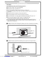
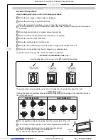
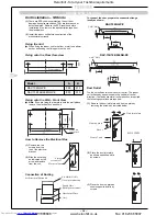
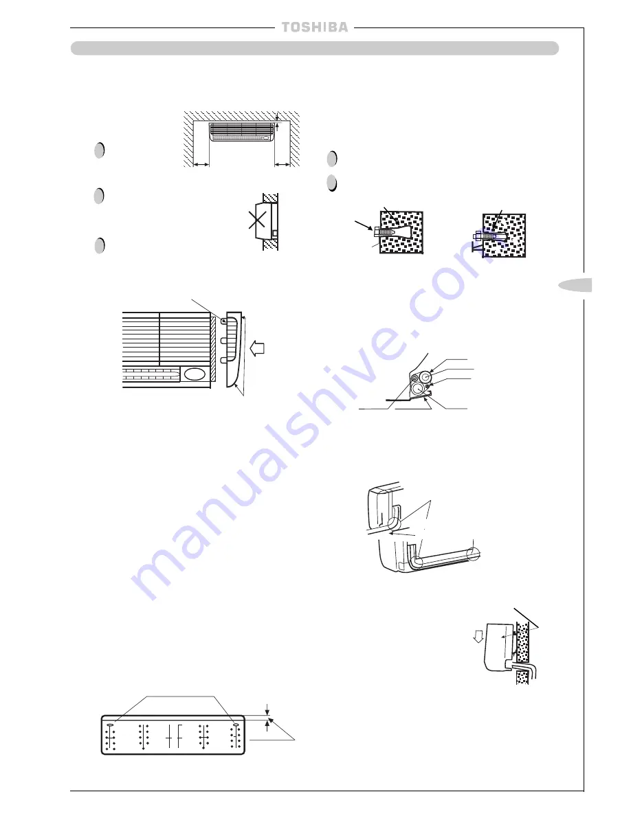
When mounting the indoor unit on the wall, follow the
instructions below:
Precautions
To drain well make
sure the unit is
mounted horizontally
or tilted slightly to the
right as seen from
the front.
Do not embed the
unit in the wall.
When installing the
side panel, remove
the air filter (on the
right or left) and
make sure the lugs
are in the lug holes.
Then, push the side
panel until it fits
securely to the unit.
l
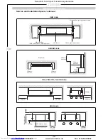
The indoor unit weighs up to 30kg including the bracket.
Before mounting the unit, make sure the wall is strong enough.
30mm or more
(Horizontal or
tilted slightly to
the right)
300mm
or more
300mm
or more
Indoor unit
Lugs
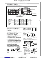
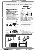
Installing Installation Bracket
l
Referring to the template, determine the location of the
indoor unit and cut the pipe hole as indicated.
l
When passing the refrigerant pipe through a wall in which a
lath is used, be sure to utilize pipe insulation.
In the case of a wooden wall (large wall):
(1) According to the distance between the indoor unit and the
ceiling, determine the vertical position (height) of the
installation bracket;
(2) Adjust the lateral position of the installation bracket with-
out changing the height so that each screw hole in the
bracket comes in the centre of a pillar or stud;
(3) In the case of a wooden wall, the distance between the
pillars is usually 900mm or 1,800mm (2,700mm) and with-
in this length, studs are located at intervals of 300 to
500mm. Be sure to install the bracket securely by driving
the accessory screws into the pillars and studs. At this
time, in order to prevent the indoor units from falling for-
ward, be sure to firmly fix the unit by tightening the screws
in the holes at both ends of the bracket (those indicated
by oblique lines on the template);
(Holes indicated by oblique lines on the template)
Wider side
(4) Make pilot holes before fitting screws.
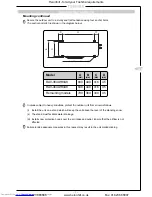
In the case of a reinforced concrete wall:
(1) In the selected areas on the reinforced concrete wall, bore
holes at intervals of 480mm, and fit anchors;
(2) Attach the installation bracket to the wall by screwing bolts
or nuts into the anchors.
However, in the case where the hole anchors are used,
the depth of the holes should be adjusted so that the nut
heads extend no more than 15mm.
Precautions
There may be a wire conduit embedded in the wall. Check the
blue prints with the builder;
Make sure that the installation bracket is fitted securely before
mounting the indoor unit.
!
!
!
!
!
Clip anchor
Bolt
Installation
bracket
Nut w/threaded
hole 8mm dia.
Less than 15mm
In the case of the pipe on the back:
l
Using the template, position the pipe hole and bore the
hole slightly downward.
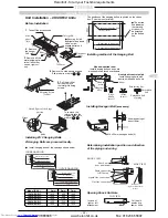
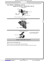
Binding of Pipes and Drain Hose
(1) In the case of the right-side pipe and the left-side pipe
bind the pipes and the drain hose as shown in the figure
below being careful that they do not protrude out of the
back of the indoor unit.
Tape
Gas pipe
Cable
Screw holding side
panel
Lower cabinet
Drain hose
(2) Make sure the drain hose does not sag.
(3) Apply proper insulation on both pipes, otherwise they
will sweat or cause a problem.
(4) Be cautious while bending the pipes to assure their
bending radius is 100mm or more.
Right-side pipe exit
While bending, bend the pipe hold-
ing the bending portion by hand
Left-side pipe exit
(5) Cut out the knockout portion for the pipe with a knife
and smooth the edge.
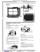
Installation
bracket
Installation of Indoor Unit
(1) Pass the pipe through the pipe hole in
the wall and mount the indoor unit on
the upper end of the installation
bracket.
(2) Move the indoor unit to the right and
left checking to see that the upper end
of the bracket is fitted in the unit.
(3) Make sure the lower end of the
pipe-holding bracket hooks the lower
cabinet to prevent the indoor unit from
moving upward.
Removal of Indoor Unit’s Right Side Panel
(1) Remove the air filter and then remove the side panel.
(2) Unfasten the right screw of the right end inlet grille.
(3) Remove the two screws holding the side panel.
(4) The side panel has lugs located on the front edge. Hold
the rear edge of the panel and pull forward to remove.
(5) To replace the removed side panel, locate lugs and push
firmly in place.
Installation of right side
panel
Liquid pipe
Side panel knockout
Concrete
wall
Hole in anchor
Concrete
wall
Hang
Heronhill - for all your Toshiba requirements
Tel: 01823 665660
www.heronhill.co.uk
Fax: 01823 665807


