~ 23 ~
GB
~ 23 ~
I
NDOOR
U
NIT
L
OCATION
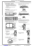
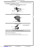
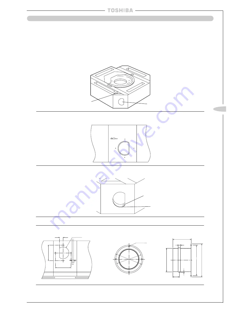
(2) Carefully cut through the slots of the ‘D’ shape with a knife ensuring the blade does not penetrate
more than 30mm.
Thermal Insulator
(5) Add a spigot to the side of the indoor unit and attach using the 4 screw holes as shown below:-
Air Inlet Spigot (ø100)
Fresh Air Inlet
Details of Cut Out Hole
(1) The cut out hole is a ‘D’ shape half-cut hole on the side of the indoor unit located on the opposite side from
the pipe work.
(3) Cut the 3 metal tabs to remove the ‘D’ shape metal part and the thermal insulator from the
indoor unit.
Metal
Fresh Air Inlet
l
These models have a cut out hole in the cabinet to enable external air to enter the indoor unit.
l
Before installing the unit, remove the cut out hole and insulation block and fit a spigot to connect the duct
before hanging the unit.
(6) Add thermal insulation around the spigot to eliminate the possibility of condensation forming on the metal sur-
faces.
Drain Pan
Insulation Block
(4) Remove the insulation block located in the drain pan, above the fresh air inlet.
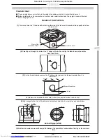
32
ø100
130
130
4-ø6
ø144
ø130
80
10
30
2
ø97
ø130
ø144
Heronhill - for all your Toshiba requirements
Tel: 01823 665660
www.heronhill.co.uk
Fax: 01823 665807


