29
3.
WIRING DIAGRAMS
3.7
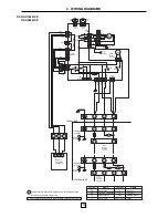
RAV-264A8-PE
51C
21
1
2
3
1
2
3
Indoor unit
Outdoor unit
Earth
Screw
Do not operate the units with magnetic contactor pushed in.
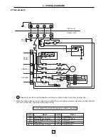
Symbol
Name
Symbol
Name
49C
47C
RCo
CM
52C
FMo
F
63F1,2
CH
Thermostat
Reverse Phase Protector
Running capacitor (fan motor)
Fuse (T5A)
Pressure Switch (2 Stage)
Compressor
Magnetic contactor
Fan motor
Crankcase heater
Overload relay
47C
49C
B
52C
A
22
3N~50Hz
Surge Absorber
6
5
4
3
2
1
6
5
4
3
2
1
52C
1
2
3
4
13
14
31
32
3
2
1
3
2
1
FM
0
3
1
6
5
4
2
BLK
WHI
RED
BLU
RC o
ORN
BLK
WHI
RED
BLU
ORN
BLK
BLU
ORN
6 3 F
2
L1
L2
L3
N
47C
S
R
T
5
6
CH
6 3 F
1
2
4
6
CM
Power
Supply
380/415V
Shows terminal block and figures show terminal numbers. Broken lines show wiring at site.
1.
2. When the three phases are not connected correctly, the reverse phase protector operates, and the unit will
not start. In this case, check the three phase wiring.
51C
F

