background image

-24-

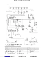
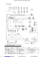
      Shows terminal block and figures show terminal numbers.

Broken lines show wiring at site.

  Do not operate the units with magnetic contactor pushed in.

TC

3.3 RAV-162KH(W)-PE

RAV-262KH(W)-PE

Remote

Controller

Indoor unit

Outdoor unit

(3 Phase model)

Earth

Screw

Earth

Screw

(1 Phase model)

F

2

F

2

(N)

CN03

(SERIAL)

CN11

(FLOAT)

(       )

K1

output

TR

CN12

CN01

(TRANS)

REMOCON

TA

CN04

(TA)

CN05

(TC)

K4      K3     K2

UL       L          M   H

YEL

RED

WHI

FM

GRN/YEL

RC

K

1

K

14

CN10

(PUMP)

F

CN07

(FAN)

(L1)

Power

Supply

220/240V


 50Hz

BLU

ORN

WHI

RED

TC

Symbol

Name

Symbol

Name

FM

Fan Motor

TA

Sensor

R

C

R

unn

ing

 C

a

pa

c

it

o

r

TC

Sensor

TR

Transformer

K1~K14

Relay

    F

Fuse (PCB)

BLK

Power

Supply

380/415V

3N 

 50Hz

Heronhill - for all your Toshiba requirements

Tel: 01823 665660

www.heronhill.co.uk

Fax: 01823 665807

Summary of Contents for RAV-162AH-PE

Page 1: ...62CH PE RAV 262AH PE RAV 262CH PE RAV 262AH8 PE RAV 362CH PE RAV 362AH8 PE RAV 462CH PE RAV 462AH8 PE SPLIT WALL TYPE HEAT PUMP RAV 162KH W PE RAV 162AH PE RAV 262KH W PE RAV 262AH PE RAV 262KH W PE RAV 262AH8 PE SPLIT CASSETTE TYPE HEAT PUMP RAV 132UH PE RAV 162UH PE 162AH PE RAV 262UH PE 262AH PE RAV 262UH PE 262AH8 PE RAV 362UH PE 362AH8 PE RAV 462UH PE 462AH PE Heronhill for all your Toshiba r...

Page 2: ...in this manual conform with the protection requirements of Directives 89 336 EEC Electromagnetic Compatibility and 73 23 EEC Low Voltage Operating conditions of units are as follows Note 1 Cooling Capacity is based on the following temperature conditions Indoor air inlet temperature 27 C DB 19 C WB Outdoor air inlet temperature 35 C DB Note 2 Heating Capacity is based on the following temperature ...

Page 3: ...an Air volume m 3 h 840 W 60 Ø 32 OD m m Heating capacity Cooling capacity k W 4 5 MODEL ITEM RAV 162BH PE Fan motor output 10 OUTDOOR UNIT Model RAV 162AH PE Appearance colour Bronze white Munsell 6Y7 5 1 Dimensions Width m m Depth m m Height m m 740 880 310 Net weight kg 61 Heat exchanger type Finned tube Outdoor fan type Propeller fan Air flow volume m 3 h 2 700 Fan motor output W 39 PH250X3 4L...

Page 4: ... pressure Standard Max motor m m A q m m A q 10 2 7 Heating capacity Condensate drain pipe diameter m m Maximum height Indoor unit height Outdoor unit height Bronze white Munsell 6Y7 5 1 790 880 310 80 Finned tube Propeller fan 3 000 63 PH330X3 4MS YH330X3 MS 2 2 2 2 Appearance colour Dimensions Height m m Width m m Depth m m Heat exchanger type Net weight Outdoor fan type Air flow volume Fan moto...

Page 5: ...ting noise SPL Charge volume Maximum height Heating capacity 3 380 415 50 3 13 8 50 External static pressure Standard Max motor 10 10 OUTDOOR UNIT Model Appearance colour Dimensions Height m m Width m m Depth m m Heat exchanger type Net weight Outdoor fan type Air flow volume Fan motor output Compressor Model Output Safety device RAV 362AH8 PE RAV 462AH8 PE Bronze white Munsell 6Y7 5 1 Bronze whit...

Page 6: ...Condensate drain pipe diameter m m INDOOR UNIT Model RAV 162CH PE Appearance colour Silky mist Capillary tube Expansion valve 50 Dimensions Height m m 188 1 030 Width m m Depth m m 640 Net weight kg 24 Heat exchanger type Finned tube Indoor fan type Multi blade fan Air volume m 3 h 780 Fan motor output W 34 Air filter Washable OUTDOOR UNIT Model RAV 162AH PE Appearance colour Bronze white Munsell ...

Page 7: ...262CH PE Appearance colour Silky mist Dimensions Height m m m m 188 Width m m 1 230 Depth m m 640 Net weight kg 28 Heat exchanger type Finned tube Indoor fan type Multi blade fan Air volume m 3 h 1 200 Fan motor output W 34 Washable 80 Air filter Refrigerant control RAV 262AH PE RAV 262AH8 PE Bronze white Munsell 6Y7 5 1 790 880 310 80 Finned tube Propeller fan 3 000 63 PH330X3 4MS YH330X3 MS 2 2 ...

Page 8: ...22 3 4 50 Capillary tube Expansion valve ø 19 ø22 Flare ø 9 5 Flare 7 5 50 49 45 41 55 R 22 3 9 50 Capillary tube Expansion valve ø 19 ø22 Flare ø 9 5 Flare 7 5 Indoor unit height 20 20 50 50 Silky mist Silky mist RAV 362CH PE RAV 462CH PE ø 20 ID ø 20 ID 50 50 240 240 1 430 1 630 640 640 39 44 Finned tube Finned tube Multi blade fan Multi blade fan 1 680 2 100 75 75 Washable Washable RAV 362AH8 P...

Page 9: ...KH W PE Appearance colour Silky mist Capillary tube Expansion valve 50 Dimensions Height m m 370 1 020 Width m m Depth m m 200 Net weight kg 19 Heat exchanger type Finned tube Transverse flow fan Air volume m 3 h 780 W 27 Washable OUTDOOR UNIT Model RAV 162AH PE Appearance colour Bronze white Munsell 6Y7 5 1 Width m m Depth m m Height m m 740 880 310 Net weight kg 61 Ø 20 ID Outdoor fan type Prope...

Page 10: ...ions Height m m m m 370 Width m m 1 350 Depth m m 200 Net weight kg 25 Heat exchanger type Finned tube Indoor fan type Transverse flow fan Air volume m 3 h 1 200 Fan motor output W 27 80 Air filter Refrigerant control RAV 262AH PE RAV 262AH8 PE 790 880 310 80 Finned tube Propeller fan 3 000 63 PH330X3 4MS YH330X3 MS 2 2 2 2 High pressure switch Fuse Bimetal thermostat Crankcase heater Inner overlo...

Page 11: ... type Air volume Fan motor output Appearance colour CEILING PANEL Model Height Width Depth mm mm mm kg m3 h Net weight Height Depth mm mm mm kg Dimensions Width Air filter Specifications are subject to change without notice RAV 132UH PE 1 220 240 50 0 066 93 0 31 0 6 R 22 Ø12 7 Flare Ø6 4 Flare Ø32 OD mm Black zinc galvanized steel Thermal insulator RBC U262PG W PE Silky mist Munsell 1Y8 9 0 5 28 ...

Page 12: ... valve 50 Dimensions Height m m 300 840 Width m m Depth m m 740 Net weight kg 29 Heat exchanger type Finned tube Indoor fan type Radial fan Air volume m 3 h 980 Fan motor output W 30 Air filter Washable OUTDOOR UNIT Model RAV 162AH PE Appearance colour Bronze white Munsell 6Y7 5 1 Dimensions Width m m Depth m m Height m m 740 880 310 Net weight kg 61 Ø 32 OD Outdoor fan type Propeller fan Air flow...

Page 13: ... 80 Air filter Refrigerant control RAV 262AH PE RAV 262AH8 PE 880 310 80 Finned tube Propeller fan 3 000 63 2 2 2 2 High pressure switch Fuse Bimetal thermostat Crankcase heater Inner overload relay High pressure switch Fuse Overcurrent relay Crankcase heater Thermostat Return Lock Dimensions Height m m Width m m Depth m m Heat exchanger type Net weight Outdoor fan type Air flow volume Fan motor o...

Page 14: ...sion valve ø 19 ø22 Flare ø 9 5 Flare 7 5 Indoor unit height 20 20 50 50 RAV 362UH PE RAV 462UH PE ø 32 OD ø 32 OD 50 50 350 350 1 130 1 130 740 740 53 53 Finned tube Finned tube Centrifugal fan Centrifugal fan 80 90 Washable Washable RAV 362AH8 PE RAV 462AH8 PE Bronze white Munsell 6Y7 5 1 Bronze white Munsell 6Y7 5 1 1 240 1 240 930 930 385 385 107 115 Finned tube Finned tube 39 63 39 63 3 0 3 7...

Page 15: ...32 Smaller side øG Refrigerant pipe connection port Provided at site Hanging bolt pitch 565 Air oulet Unit dimension A Hanging bolt pitch B Ceiling opening D Panel outer dimension E Model A B F G H J K M N RAV 162BH PE 700 750 12 7 6 4 252 280 280 1 2 RAV 262BH PE 10001050 15 9 9 5 252 580 290 2 3 RAV 362 462BH P 13501400 19 0 9 5 252 930 310 3 4 Unit mm Indoor unit Provide an inspection hole arou...

Page 16: ...uter hanging bolt pitch Refrigerant piping joint Gas øG Hanging bolt Less than 40 Knock out holes for piping and wiring Hard vinyl chloride pipe inner dia 20mm Drain piping joint Refrigerant piping joint Liquid øF Inner hanging bolt pitch Hanging bolt pitch Greater than 500 Hanging bolt pitch Hanging bolt Less than 40 Hanging bolt hole 4 12x25 Slot Alternative Knock out hole for drain piping Hangi...

Page 17: ...00 Space required for service Anchor bolt hole 4 10x20 long hole Long hole RAV 262KH W PE RAV 162KH W PE Long hole Anchor bolt hole 4 10x20 long hole Piping hole Knockout hole Model A B C RAV 162KH W P 1020 12 7 6 4 RAV 262KH W P 1350 15 9 9 5 Installation board mounting bolt hole location 2 3 Indoor Unit RAV 162KH W PE RAV 262KH W PE Heronhill for all your Toshiba requirements Tel 01823 665660 ww...

Page 18: ...Drain pipe connection port Power supply connection port Smaller side B Refrigerant pipe connection port Larger side A Refrigerant pipe connection port More than 15 2 4 Indoor Unit Unit model RAV 132UH PE RAV 162UH PE RAV 262UH PE Panel model RBC 262PG W PE 2 Ceiling panel Heronhill for all your Toshiba requirements Tel 01823 665660 www heronhill co uk Fax 01823 665807 ...
Page 19: ...nnection port Larger side ø19 Power supply connection port Drain pipe connection port Water supply check port Hanging bolt Remote controller Long hole Door Ceiling panel Ceiling opening 1230 Panel outer dimension 1290 Z View Panel outer dimension 840 Ceiling opening 780 Z Heronhill for all your Toshiba requirements Tel 01823 665660 www heronhill co uk Fax 01823 665807 ...
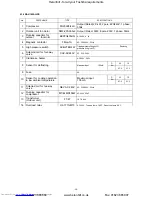
Page 20: ...iping joint Anchor bolt hole Blow out guide mounting hole 4 ø3 embossing Space for wiring and piping Outlet Space for wiring and piping Outlet Space required for service When installed with the outlet faced to the wall side When installed with the inlet faced to the wall side Unit mm 4 12 x 18 long hole Air outlet Both sides Carrying handle Electric parts box Earth screw Terminal cover M6 A B Hero...

Page 21: ... Terminal cover Carrying handle Front side only Air outlet Air outlet Knock out hole ø 40 Blow out guide mounting hole 8 ø3 embossing Outlet Space for wiring and piping Space for wiring and piping Outlet When installed with the inlet faced to the wall side When installed with the outlet faced to the wall side Space required for service 2 7 Outdoor Unit RAV 362AH8 PE RAV 462AH8 PE Earth screw M6 He...

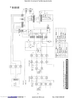
Page 22: ...L M H C N 0 7 FAN K 1 output FM FM BLK YEL BLU RED BRW G R N Y E L G R Y RC W H I R E D F a n s p e e d increase option C o n n e c t o r a s s e m b l y accessory YEL BLU ORN ORN RED BLK RED ORN BRW YEL BLU BLK Earth Screw Earth Screw C N 0 1 TRANS C N 0 4 TA C N 0 5 T C YEL BLU BLK ORN F 2 F 2 F Power Supply 380 415V 3N 50Hz Symbol Name Symbol Name FM Fan Motor K 1 14 Relay RC Running Capacitor ...

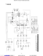
Page 23: ...K 2 UL L M H C N 0 7 FAN K 1 output C N 0 1 TRANS C N 0 4 TA C N 0 5 T C F LI TR Y E L B L U O R N B L K G R N Y E L FM R E D GM K 11 C N 0 9 L O U V E R C N 1 1 FLOAT C N 0 3 S E R I A L N F 2 Power Supply 380 415V 3N 50Hz G R Y W H I RC Earth Screw Earth Screw Symbol Name Symbol Name FM Fan Motor TA Sensor RC Running Capacitor TC Sensor TR Transformer GM Geared Motor F Fuse PCB K1 K14 Relay K 1 ...

Page 24: ...C N 0 3 S E R I A L C N 1 1 FLOAT K 1 output TR C N 1 2 C N 0 1 TRANS R E M O C O N TA C N 0 4 TA C N 0 5 T C K 4 K 3 K 2 UL L M H YEL RED WHI FM G R N Y E L RC K 1 K 14 C N 1 0 PUMP F C N 0 7 FAN L1 Power Supply 220 240V 50Hz BLU ORN WHI RED TC Symbol Name Symbol Name FM Fan Motor TA Sensor RC Running Capacitor TC Sensor TR Transformer K1 K14 Relay F Fuse PCB BLK Power Supply 380 415V 3N 50Hz Her...

Page 25: ...MP L1 N CN11 FLOAT F K 1 C N 0 1 TRANS R E M O C O N C N 1 2 C N 0 4 TA C N 0 5 T C TA C N 0 7 FAN TC UL L M H V I O Y E L B L U O R N K 1 output FM GM C N 0 9 L O U V E R G R N Y E L WHI B L U O R N B L K V I O WHI RC DM 43 CS 43 K 11 RED RED YEL TR Symbol Name Symbol Name FM Fan Motor 43 Relay RC Running Capacitor K1 K14 Relay TR Transformer GM Geared Motor TA Sensor CS Float Switch TC Sensor DM...

Page 26: ...C N 0 9 L O U V E R L1 N C N 0 3 S E R I A L C N 1 1 FLOAT GM K 1 output C N 1 0 PUMP K 14 K 1 TR C N 0 1 TRANS R E M O C O N C N 1 2 C N 0 4 TA C N 0 5 T C TA TC K 4 K 3 K 2 UL L M H R E D W H I RC WHI G R N Y E L FM B L U O R N B L K V I O K 11 CS F Y E L B L U O R N B L K C N 0 7 FAN RED YEL Symbol Name Symbol Name FM Fan Motor 43 Relay RC Running Capacitor K1 K14 Relay TR Transformer GM Geared...

Page 27: ...3 K 2 R E M O C O N C N 1 2 C N 0 4 TA C N 0 5 T C TA TC UL L M H B L K O R N FM R E D GM RC W H I C N 1 1 FLOAT C N 0 3 SERIAL F C N 1 0 PUMP K 11 43 43 CS Spark Killer DM C N 0 7 FAN K 1 K 14 C N 0 9 L O U V E R G R Y Symbol Name Symbol Name FM Fan Motor 43 Relay RC Running Capacitor K1 K14 Relay TR Transformer GM Geared Motor TA Sensor CS Float Switch TC Sensor DM Drain Motor F Fuse PCB LI N B ...

Page 28: ... site Don t operate the units with magnetic contactor pushed Symbol Name Symbol Name Symbol Name 20SF Solenoid Coil 4 Way Valve CM Compressor F2 Fuse T5A RY05 07 Relay 52C Magnetic Contactor 63H High Pressure Switch 51C Overload Relay FMo Fan Motor Out door CH Crank Case Heater 20SR Solenoid Coil 2 Way Valve TL Sensor F Fuse on PCB RCc Running Capacitor Compressor TE Sensor TR Transformer RCo Runn...

Page 29: ...te Don t operate the units with magnetic contactor pushed Symbol Name Symbol Name Symbol Name 20SF Solenoid Coil 4 Way Valve CM Compressor F2 Fuse T5A RY05 07 Relay 52C Magnetic Contactor 63H High Pressure Switch 49C Inner Overload Relay FMo Fan Motor Out door CH Crank Case Heater 20SR Solenoid Coil 2 Way Valve TL Sensor F Fuse on PCB RCc Running Capacitor Compressor TE Sensor TR Transformer RCo R...

Page 30: ...correctly the reverse phase protector operates and the unit will not start In this case check the three phase wiring Don t operate the units with magnetic contactor pushed Symbol Name Symbol Name Symbol Name 20SF Solenoid Coil CM Compressor F2 Fuse T5A RY05 07 Relay 52C Magnetic Contactor 63H High Pressure Switch 49C Inner Overload Relay FMo Fan Motor Out door CH Crank Case Heater 51C Overload Rel...

Page 31: ...inal block and figures show terminal numbers Broken lines show wiring at site Don t operate the units with magnetic contactor pushed Symbol Name Symbol Name Symbol Name 20SF Solenoid Coil CM Compressor 63H High Pressure Switch RY05 07 Relay 52C Magnetic Contactor CH Crank Case Heater 49C Inner Overload Relay FM01 02 Fan Motor Out door F Fuse on PCB 51C Overload Relay TL Sensor TR Transformer RC01 ...

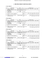
Page 32: ...nger temp DTN C103J40 Maximum input 34mA C 12 0 25 50 62 29 32 82 10 0 3 59 4 4 RAV 462BH PE KW KW KW KW KW KW KW KW No PARTS NAME TYPE SPECIFICATIONS 1 Indoor unit fan motor STF 200 100 4 Output Rated 100W 4 pole 200V 1 phase 50Hz 2 Running capacitor for indoor fan motor EAG40M505UF AC 400V 5µF 3 Transformer Indoor unit ST 9586 187 264V 4 Sensor for room temperature Maximum input 38mA C 15 20 25 ...

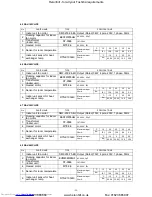
Page 33: ...ut 34mA C 12 0 25 50 62 29 32 82 10 0 3 59 4 7 RAV 362CH PE No PARTS NAME TYPE SPECIFICATIONS 1 Indoor unit fan motor SMF 230 75 4U Output Rated 75W 4 pole 230V 1 phase 50Hz 2 Running capacitor for indoor fan motor EEP2W255HQ AC 400V 2 5µF 3 Transformer Indoor unit ST 9586 187 264V 4 Geared motor MT8 3 6 AC 240V 3W 5 Sensor for room temperature Maximum input 38mA C 15 20 25 30 40 16 1 12 6 10 0 8 ...

Page 34: ...m input 34mA C 12 0 25 50 62 29 32 82 10 0 3 59 4 10 RAV 262KH W PE No PARTS NAME TYPE SPECIFICATIONS 1 Indoor unit fan motor AF 230 27 4R Output Rated 27W 4 pole 230V 1 phase 50Hz 2 Running capacitor for indoor fan motor EEP2H155HQA AC 400V 1 5µF 3 Transformer Indoor unit ST 9586 187 264V 4 Sensor for room temperature Maximum input 38mA C 15 20 25 30 40 16 1 12 6 10 0 8 0 5 2 5 Indoor unit sensor...

Page 35: ... 3 Transformer for Indoor unit ST 9586 AC187 264V 4 Relay LY2F AC240V 2ab 5 Geared motor MT8 3 3 AC 240V 3W 6 Drain pump PAD 416A34TF AC230V 0 2A 7 Float switch FS 085 003B AC230V 0 5A 8 Sensor for room temperature Maximum input 38mA C 15 20 25 30 40 16 1 12 6 10 0 8 0 5 2 9 Indoor unit sensor for heat exchanger temp DTN C103J40 Maximum input 34mA C 12 0 25 50 62 29 32 82 10 0 3 59 No PARTS NAME T...

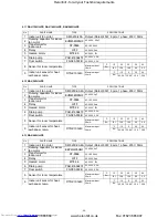
Page 36: ...23kg cm G 6 Soleniod coil for four way valve CHV AC240V AC 220 240V 7 Crankcase heater AC 240V 28W 8 Sensor for defrosting Maximum input 15 5mA C 12 10 67 5 21 3 9 Fuse 5A 10 Sensor for cooling operation in low ambient temperature Maximum input 15 5mA C 12 10 67 5 21 3 11 Soleniod coil for two way valve NEV AC 240V AC 220 240V 50Hz 12 Running capacitor for compressor MT 44MP456W AC 440V 45µF 13 Tr...

Page 37: ...ure 30kg cm G Resetting pressure 23kg cm G 6 Soleniod coil for four way valve CHV AC240V AC 220 240V 7 Crankcase heater AC 240V 28W 8 Sensor for defrosting Maximum input 15 5mA C 12 10 67 5 21 3 9 Fuse 5A 10 Sensor for cooling operation in low ambient temperature Maximum input 15 5mA C 12 10 67 5 21 3 11 Bimetal thermostat CS 7 Trippingtemp 110 C Resettingtemp 90 C 12 Solenoid coil for two way val...

Page 38: ...pressure switch ACB 2TBO4W Tripping pressure 30kg cm G Resetting pressure 23kg cm G 6 Soleniod coil for four way valve CHV AC240V AC 220 240V 7 Crankcase heater AC 240V 28W 8 Sensor for defrosting Maximum input 15 5mA C 12 10 67 5 21 3 9 Fuse 5A 10 Sensor for cooling operation in low ambient temperature Maximum input 15 5mA C 12 10 67 5 21 3 11 Thermostat CS 7 Tripping temp 120 C Resetting temp 90...

Page 39: ... contactor FMSA 1 AC 230V 50Hz Tripping current 9A Resetting manual 5 High pressure switch ACB 2TBO4W Tripping pressure 30kg cm G Resetting pressure 23kg cm G 6 Soleniod coil CHV AC240V AC 220 240V 7 Crankcase heater AC 240V 58W 8 Outdoor unit sensor for heat exchanger temp Maximum input 15 5mA C 12 10 67 5 21 3 9 Transformer for outdoor unit FT 67 AC 187 264V 10 Fuse 5A 11 Sensor for cooling oper...

Page 40: ...contactor FMSA 1 AC 230V 50Hz Tripping current 12A Resetting manual 5 High pressure switch ACB 2TBO4W Tripping pressure 30kg cm G Resetting pressure 23kg cm G 6 Soleniod coil CHV AC240V AC 220 240V 7 Crankcase heater AC 240V 58W 8 Outdoor unit sensor for heat exchanger temp Maximum input 15 5mA C 12 10 67 5 21 3 9 Transformer for outdoor unit FT 67 AC 187 264V 10 Fuse 5A 1 1 Sensor for cooling ope...

Page 41: ...r side ø6 4mm 1 4 Strainer Heat exchanger Indoor unit Distributor strainer capillary tube ø2 0 x 200l x 2P Refrigerant pipe Larger side ø12 7mm 1 2 5 1 Indoor unit RAV 132UH PE Heronhill for all your Toshiba requirements Tel 01823 665660 www heronhill co uk Fax 01823 665807 ...
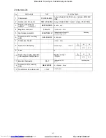
Page 42: ... joint Capillary tube ø0 8 x 1000l x 1P High pressure switch Refrigerant pipe Smaller side ø6 4mm 1 4 Outdoor unit Strainer Heat exchanger Indoor unit Distributor 2 way valve Heat exchanger Strainer Four way valve Accumulator Compressor Refrigerant pipe Larger side ø12 7mm 1 2 5 2 Indoor unit RAV 162BH PE RAV 162CH PE RAV 162KH W PE RAV 162UH PE Outdoor unit RAV 162AH PE Distributor strainer capil...

Page 43: ...ling Heating Packed valve Strainer Capillary tube Dryer Expansion valve TE sensor Check joint Four way valve High pressure switch Compressor Accumulator Strainer Outdoor unit Heat exchanger Indoor unit Strainer TC Sensor Refrigerant pipe Smaller side ø9 5mm 3 8 Refrigerant pipe Larger side ø15 9mm 5 8 Check Valve 2 way valve Distributor Heat exchanger Bypass capillary tube l Outdoor unit RAV 262AH...

Page 44: ...cked valve Strainer Capillary tube ø2 6 x 700l x 1P Dryer Expansion valve Check valve Check valve TE sensor Check joint Four way valve High pressure switch Strainer Outdoor unit Indoor unit Heat exchanger TC Sensor Strainer Cooling Heating Refrigerant pipe Larger side ø15 9mm 5 8 Distributor TL sensor Heat exchanger Compressor Accumulator Muffler Distributor strainer capillary tube l Cooling Heati...

Page 45: ...k joint Four way valve High pressure switch Outdoor unit Indoor unit Capillary tube Dryer Bypass Capillary tube Heat exchanger Distributor strainer capillary tube Strainer TC Sensor Cooling Heating Refrigerant pipe Larger side ø19mm 3 4 Distributor TL sensor Heat exchanger Accumulator Compressor Muffler 5 5 Indoor unit RAV 362BH PE RAV 362CH PE RAV 362UH PE RAV 462BH PE RAV 462CH PE RAV 462UH PE O...

Page 46: ... OFF TIME Temperature setting AUTO LOW MED HIGH Auto Fan Speed Control Low Fan Speed Med Fan Speed High Fan Speed AUTO COOL HEAT 1 HEAT 2 FAN ONLY LED RED MODE FAN TIME TIMER Auto Changeover Cooling Heating Heating with indoor fan operation at defrost Fan only 1 Present Time Adjust 2 ON Time setting 3 OFF Time setting Run Stop TEMP Heronhill for all your Toshiba requirements Tel 01823 665660 www h...

Page 47: ...lically CONTINUE Þ ON Þ OFF Þ ON Þ OFF Þ ON OFF Þ CYCLE Þ If pushed continuously the timer mode will be changed in one stop every 0 5 sec Pressing this key for 0 5 sec provides MALFUNCTION CHECK indicating on liquid crystal the contents of inspection in the sequence of times of compressor on Þ contents of malfunction for 1 unit Þ contents of malfunction for 2 unit Þ Pressing this key for 5 sec giv...

Page 48: ... will go back to the present time 6 3 Timer operation Continuous operation and timer operations are available The setting of timer operation can be done as follows ON OFF ON Þ OFF OFF Þ ON ON Þ OFF CYCLE 6 3 1 Time display The present time is always displayed The display of the ON OFF time is only in setting the time Once set it will not change even after carrying out the timer operation until the...

Page 49: ...is displayed Timer OFF operation 1 TIMER OFF is applied 2 ON OFF key is pressed Then LED is lighted and the operation starts with OPERATION displayed on the liquid crystal 3 When the set OFF TIME comes the operation stops and the LED OPERATION display goes off with TIMER OFF displayed ON OFF timer operation 1 TIMER ON Þ OFF or TIMER ON OFF is applied 2 ON OFF key is pressed LED comes on and the op...

Page 50: ...perature sensor Compressor stays off in heating it is not turned off in cooling Short circuit in room temperature sensor 2 Indoor fan stays off in heating 0d Open ciruit in indoor heat exchanger sensor Outdoor fan continues ON OFF operation in heating Short circuit in indoor heat exchanger sensor 3 Though indoor unit operates outdoor unit remains off 04 Abnormality in connecting cable between indo...

Page 51: ...62 x 0 16 x 10 4 164 Display in 7 segments Check code information No display is made if there is no fault Ex in case of the number of times of compressor actuations of 164 Unit number Check code The first detected The last detected Ex In case of room temperature sensor of No 1 unit in trouble For No 15 unit firstly heat exchanger temperature sensor and secondly float switch circuit are faulty hexa...

Page 52: ...g heating operation 2 When transmitting instruction for stopping compressor by freeze preventing control Operation continuing 1 Compressor case thermostat IOL OL operation contactor OFF compressor stops AH8 Models contactor ON compressor stops AH Models 2 Indoor heat exchange sensor out of place 3 Check the indoor PC board 4 Check that service valves are OPEN Outdoor unit stops indoor fan L 1 Chec...

Page 53: ... OF OUTDOOR UNIT Full stop 1 Check the compressor 2 Check the wiring of compressor lack of phase short circuit 3 Check the voltage 4 Check the outdoor PC board WRONG WIRING OF REMOTE CONTROL UNIT Indoor unit does not operate at all Full stop 1 Check the wiring between remote control unit and indoor unit 2 Check the indoor unit PC board FLOAT SWITCH Float circuit out of position break Outdoor unit ...

Page 54: ...ction check 6 5 1 Using LED display on outdoor PC board LED display vs check code POSITIONS OF DIP SWITCH AND LED Dip Switch SW01 LED D04 orn Serial input D05 grn Serial output PC Board 18 Temp sensor TE faulty 19 Temperature sensors TD TL open short circuit 21 High pressure switch fault Heronhill for all your Toshiba requirements Tel 01823 665660 www heronhill co uk Fax 01823 665807 ...

Page 55: ... one Number of protective device operations two Number of protective device operations three LEDs 3 4 flashing 1Hz faults shown below Number of protective device operations four Full stop 18 Temperature sensor TE faulty 19 Temperature sensors TD TL open short circuit 21 Hi h ressure switch fault Table 1 Table 2 LED Status on 5Hz flash 1Hz flash off Heronhill for all your Toshiba requirements Tel 0...

Page 56: ...D Status of compressor 1 2 3 4 Stop Operating Dip switch settings LED Status of compressor 1 2 3 4 Stop Operating Table 3 Table 4 Heronhill for all your Toshiba requirements Tel 01823 665660 www heronhill co uk Fax 01823 665807 ...

Page 57: ...ration mode is changed over according to operation mode select instruction from the remote controller Operation change over Stopping air conditioner Performing automatic change over Performing cooling operation Performing heating operation Performing heating operation with indoor fan operation at defrosting Performing fan only operation Controlling room temperature 3 1 Adjusting range C Remote con...

Page 58: ...mperature detection of Tc sensor When starting the operation the point P is made 3 C When J zone is detected timer counting starts When K zone is detected timer counting is discontinued and held on When I zone is detected timer is cleareed for returning back to ordinary operation When timer counting becomes full time the ourdooor unit stops and the point P is changed to 12 C to be covered by check...

Page 59: ...f H α discontinued When stopping operation When changing over operation When performing heating operation the following control is done based on temperature detection of Tc sensor In M zone release signal is transmitted Outdoor fan is controlled in accordance with the diagrams below The control point for A and C can be chosen from the below table Release ON Release OFF O N Release signal OFF For 3...

Page 60: ...g 12 1 is made based on outdoor heat 12 1 exchange temperature Te 12 2 When cumulative working time 12 2 of the compressor in A zone 12 2 has amounted to 55 minutes 12 2 defrosting operation starts 12 2 25 minutes initially 12 3 The longest defrosting time is 12 3 12 minutes 60 sec in the case 12 3 of turning into B zone and 12 3 immediate returning back when 12 3 C zone is reached If the high pre...

Page 61: ...n same setting condition by one remote controller However thermo control function is independent Respective delayed start time for preventing simultaneous large starting current can be obtained by different setting of the unit No switch on the indoor PC board Air quantity A Zone H B Zone Per 1 minute and 30 sec 1 wave C Zone Maintain D Zone Per 20 sec 1 wave 14 1 Control on outdoor fan is made 14 ...

Page 62: ...his is a circuit for transmitting and receiving the signals between the indoor and outdoor units in serial signal As 230V is used for transmitting the signal the microcomputer section is insulated by means of photo coupler with the voltage reduced to 5V With AC interrupt judgement is made as to the presence or absence of serial signal based on the reference pulse taken out from the voltage across ...

Page 63: ... 0V and starts its operation with the signal of 5V Watchdog timer output gives the signal from microcomputer as illustrated below This indicates that the microcomputer is working in normal routine For ex ample if the microcomputer is straying due to noise and so on this waveform is not produced In case there is no waveform it plays the role of restoring normal condition by inputting the resetting ...

Page 64: ...ntroller At and the signals as illustrated below are output 8 8 Optional circuit A circuit which allows for the take out of the signals of abnormal operation and Compressor ON Point is a LED which lights at abnormal The connector pin 4 outputs 12V When you want to see the signal of compressor ON you can do it simply with the circuit below Comp Compressor ON Abnormal Operation Heronhill for all you...

Page 65: ...ay circuit The relay circuit consists of the diagram above The relay performs the following functions RY01 Main switching relay RY02 Changing over H M of fan RY03 L tap of fan RY04 UL tap of fan RY11 Turning louver on and off RY14 Turning drain pump on and off Fan Control Output Heater Louver Output Drain pump To CPU To CPU Model Change TA Shift TC Shift Unit Number R Y 0 3 A J E 6 4 1 2 R Y 0 1 A...

Page 66: ... 2 3V 3 8V TL 2 3V 3 8V When are at GND or 5V the sensors are either open or short circuited 9 3 12V power source circuit Outdoor PC board produces full wave rectification by diode bridge DB50 followed by the provision of tran sistor Q50 produces DC power source at 12V 9 4 5V watchdog timer circuit Basically the same description as the indoor PC board applies provided however that the reset circui...

Page 67: ...5V 0 Output 5V 0 9 7 Abnormality detecting circuit When high pressure switch is operated abnormality is detected to stop the compressor 9 8 Relay circuit The relay circuit consists of the diagram on the right hand side RY05 4 way valve ON OFF RY07 Magnetic switch ON OFF abnormal input N Abnormal input High Pressure Switch Serial L Serial output AC Serial input Relay control circuit Heronhill for a...

Page 68: ... 10 Lightning surge protection circuit The circuit on the right protects the PCB from damage caused by a lightning surge Varistors are connected between the live and neutral and live and earth lines to protect against voltage surges Waveform obtained between and T Example shown is for 4 waves To CPU Wiring for 2 fan motors RED WHI WHI N I Heronhill for all your Toshiba requirements Tel 01823 66566...

Page 69: ...until D08 Led illuminate remove the short The led will then extinguish and the indoor unit will start After a couple of minutes the outdoor unit will start LEDs D07 and D10 will illuminate OPERATION STOP orange LED flashing orange LED off Short pins CN28 with CN29 LEDs D08 and D10 will extinguish After indoor unit has stopped D07 will extinguish ƒ Reset DSW01 bits 1 2 to OFF position for normal op...

Page 70: ...ply to the outdoor unit Remove the electrical parts cover from the indoor unit Pull out the connector of R phase red lead wire from terminal and connect it with the connector of lead wire for fan motor K1 output red Note If the indoor unit is a cassette model the float switch connector must be removed from the PCB Replace the electrical parts cover on the indoor unit On the outdoor unit PCB change...

Page 71: ...of each unit is respectively delayed to prevent simultaneous starting current 13 WIRING FOR GROUP OPERATION Up to 16 units can be controlled as a group by one remote controller Align the phase sequence of the power supply to all outdoor units Connect the terminals A B C on both of the remote controller and the indoor unit of No 1 unit ƒ Connect terminals B C on both indoor units of No 1 and No 2 u...

Page 72: ... 10 00 12 50 4 73 7 46 10 50 13 13 4 95 7 81 11 00 13 75 5 18 8 17 11 50 14 38 5 40 8 52 12 00 15 00 KW RAV 162AH PE RAV 262AH PE RAV 262AH8 PE RAV 362AH8 PE RAV 462AH8 PE 6 00 9 48 12 96 16 56 5 75 9 09 12 42 15 87 5 50 8 69 11 88 15 18 5 25 8 30 11 34 14 49 5 00 7 90 10 80 13 80 4 75 7 51 10 26 13 11 4 50 7 11 9 72 12 42 4 25 6 72 9 18 11 73 4 00 6 32 8 64 11 03 3 75 5 93 4 10 10 35 3 50 5 53 7 ...

Page 73: ... Cooling Capacity Ratio Heating Capacity Ratio Outdoor Unit Height H m Cooling Capacity Ratio Heating Capacity Ratio Piping Length m Piping Length m Indoor Unit Outdoor Unit The broken line shows in case the piping length is 30m or less Piping Length m Piping Length m Heronhill for all your Toshiba requirements Tel 01823 665660 www heronhill co uk Fax 01823 665807 ...

Page 74: ...st be raised one rank eq 19 0 22 2 MODEL No of discharge way 4 way 3 way 2 way Air flow direction A B C D A B C A B RAV 132 162 262UH PE Air volume ratio 30 30 30 10 33 33 33 50 50 RAV 362 462UH PE Air volume ratio 40 40 10 10 40 40 20 50 50 Piping joint Ceilling panel Not to block the A and B direction longer side Air flow direction volume ratio 5 m Note When installing more than one unit in the ...

Page 75: ...ption 2 01 4 3 1 6 0 3 9 4 Connector 9P 2 0 2 4 3 0 1 9 6 0 4 Holder Sensor 2 0 3 4 31 2 01 4 9 Fan Multi Blade 2 0 4 4 3 A 2 1 0 0 9 Mo tor Fa n RAV 16 2 BH PE 4 312 151 6 Mo to r Fa n RAV 2 62 B H P E 4 31 2 15 2 8 Mo to r Fa n RAV 3 62 B H P E 4 31 2 15 3 5 Mo to r Fa n RAV 4 62 B H P E 2 0 5 4 3 A 4 4 0 0 2 Eva p ora to r RAV 1 62 B H P E 4 3 1 4 4 6 7 9 Eva p ora tor RAV 2 62 B H P E 4 3 1 4 ...

Page 76: ... 3 1 4 4 6 3 9 A sm E va p o ra tor RAV 162CH PE 2 2 3 4 3 A 4 4 0 0 4 A sm E va p o ra tor RAV 262CH PE 2 2 3 4 3 1 A 4 0 0 5 A sm E va p o ra tor RAV 362CH PE 2 2 3 4 3 1 4 4 6 5 0 A sm E va p o ra tor RAV 462CH PE 2 2 4 4 3 15 5 13 8 MF Capacitor RAV 162 262 362CH PE 2 2 4 4 3 15 5 12 0 MF Capacitor RAV 462CH PE 2 2 5 4 3 A 6 9 0 0 4 Remote Control 2 2 6 4 3 17 0 19 7 A sm Hose 2 2 7 4 31 721 2...

Page 77: ...on 2 31 4 3 A 8 8 0 0 2 Manual Location No Part No Description 201 4 3 A 6 9 0 0 4 Remote Controller 2 0 3 4 3 12 1 47 4 M o tor RAV 162KH W PE 2 0 3 4 31 214 91 M o tor RAV 262KH W PE 2 0 4 4 3 A 6 9 0 0 2 PC Board 2 0 5 4 3 A 5 8 0 0 2 T ra n sfo rm e r P o w e r 2 0 6 4 3 A 6 0 0 0 1 T e rm ina l 4 P 2 0 7 4 31 551 01 Capacitor Electrolytic 2 0 8 4 3 A 6 0 0 0 2 T e rm im a l 3 P 2 0 9 4 3 1 2 ...

Page 78: ... 4 31 501 18 S e n so r T A Location No Part No Description 2 2 9 4 3 15 0 19 9 S e n so r T C 2 3 0 4 31 512 17 Float Switch 2 3 3 4 3 A 5 8 0 0 2 T ra n sfo rm e r P o w e r 2 3 5 4 3 16 0 25 1 Terminal Block 2 3 6 4 3 A 6 0 0 0 1 T e rm in a l 4 P 2 3 7 4 3 A 6 0 0 0 2 T e rm in a l 3 P 2 3 9 4 3 A 6 2 0 0 1 Cover Remocon 2 4 0 4 3 A 6 9 0 0 2 PC Board 241 4 31 721 18 Drain Pan RAV 132UH PE 4 3...

Page 79: ...RAV 462UH PE 2 31 4 3 0 4 7 5 2 7 Ca p illa ry T u b e 2 0 DIA 2 3 3 43150 111 Sensor 2 3 4 4 31 5 01 4 8 Sensor Location No Part No Description 2 3 5 4 3 15 1 20 3 Float Switch 2 3 7 4 3 0 5 5 2 9 2 Capacitor Electrolytic RAV 362UH PE 2 3 7 4 3 1 5 5 0 8 0 Capacitor Electrolytic RAV 462UH PE 2 3 9 4 3 A 5 8 0 0 2 T ra n sfo rm e r P o w e r 2 4 0 4 3 A 6 0 0 0 1 T e rm ina l 4 P 241 4 3 A 6 0 0 0...

Page 80: ...take Grill Assy RBC U462PG W PE 211 43409067 Holder Shaft Location No Part No Description 214 43121550 Geared Motor 215 43480533 Air Filter RBC U262PG W PE 43480531 Air Filter RBC U462PG W PE 217 43409070 Grille Outlet RBC U262PG W PE 43409069 Grille Outlet RBC U462PG W PE 220 43409075 Grille Outlet Small 227 43497009 Spring Holder RBC U462PG W PE Heronhill for all your Toshiba requirements Tel 01...

Page 81: ...Holder Sensor TE 21 43169600 Holder 22 43148105 Accumulator Location No Part No Description 23 43145082 Dryer 24 43155080 Capacitor Electrolytic 25 43041845 Compressor AC220 240V 50Hz PH250X3 4LS 26 43146454 Packed Valve 1 4 27 43146406 Packed Valve 1 2 28 43147321 Check Joint 29 43146424 Expansion Valve 30 43046198 Coil 2 Way Valve 31 43146283 Checked Valve 33 43A58003 Transforrmer Power 34 43046...

Page 82: ...r TE 21 43169600 Holder 22 43148114 Accumulator Location No Part No Description 23 43145082 Dryer 24 43155080 Capacitor Plastic Film 25 43140318 Compressor PH330X3 4MS 26 43146451 Packed Valve 3 8 27 43146417 Packed Valve 5 8 28 43147321 Check Joint 29 43146433 Expansion Valve 30 43046156 Checked Valve 31 43146283 Checked Valve 33 43A58003 Transforrmer Power 34 43046151 Valve 2 Way 35 43046198 Coi...

Page 83: ...Holder Thermostat Bimetal 43 43146459 Capillary Tube 44 43107215 Holder Sensor TL Location No Part No Description 1 43120156 Fan Propeller 2 43A21002 Motor Fan AC 230V 50Hz 3 43A43002 Condenser 4 43049132 Base Spring B 5 43149198 Spring Buffer 6 43149212 Base Spring A 7 43A69003 PC Board 8 43A49001 Switch High Pressure 9 43060479 Terminal 4P 10 43A60005 Terminal 4P 1 1 43A60001 Terminal 4P 12 4315...

Page 84: ...r Power Location No Part No Description 1 43A21002 Motor AC 230V 50Hz Fan 2 43A21003 Motor AC 230V 50Hz Fan 3 43120156 Fan Propeller 4 43A19001 Guard Fan 5 43143638 Condenser Lower RAV 362AH8 PE 5 43143636 Condenser Lower RAV 462AH8 PE 6 43143639 Condenser Upper RAV 362AH8 PE 6 43143637 Condenser Upper RAV 462AH8 PE 7 43047492 Capillary Tube RAV 362AH8 PE 7 43047527 Capillary Tube RAV 462AH8 PE 8 ...

Page 85: ... 89 Heronhill for all your Toshiba requirements Tel 01823 665660 www heronhill co uk Fax 01823 665807 ...

Reviews: