-54-
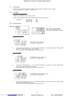
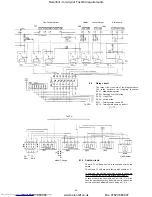
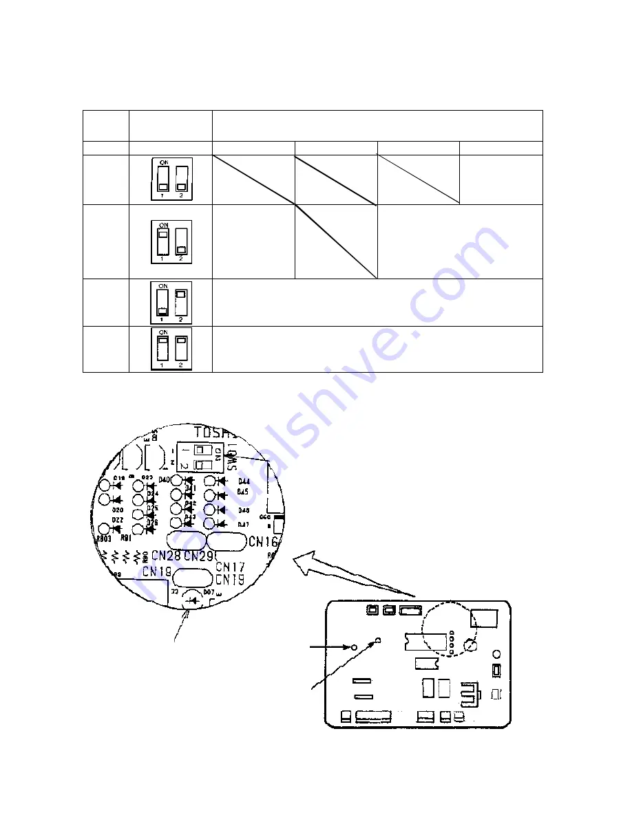
Dip switch
settings
( D S W 0 1 )
LED
1 (RED)
2 (YELLOW)
3 (YELLOW)
4 (YELLOW)
Table-1
Table-2
Number of protective device
operations
Table-3
Serial input data
Table-4
Serial output data
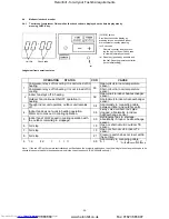
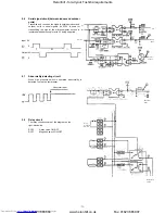
6.5
Malfunction check
6.5.1
Using LED display on outdoor PC board
LED display vs. check code
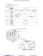
POSITIONS OF DIP SWITCH AND LED
Dip Switch (SW01)
LED
D04 (orn)
Serial input
D05 (grn)
Serial output
PC Board
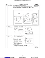
18 Temp. sensor (TE)
faulty
19 Temperature
sensors TD/TL
open/short circuit.
21 High pressure
switch fault
Heronhill - for all your Toshiba requirements
Tel: 01823 665660
www.heronhill.co.uk
Fax: 01823 665807


