No.
4
Part name
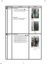
Side cabinet
(right)
Procedure
Remarks
1.
Detachment
1) Following to work of Detachment of
1 .
2)
Remove
the
screws
from the side panel (right)
and the inverter box.
(Ø4 ×
10
,
2
pcs.)
3) Remove the screws from the side panel (right)
and the valve fixing plate, (Ø4 × 10, 2 pcs.)
4) Remove the screws from the side panel (right)
and the piping panel (rear), (Ø4 × 10, 2 pcs.)
5) Remove the screws from the side panel (right)
and the base plate, (Ø4 × 8, 2 pcs.)
6) Remove the screws from the side panel (right)
and the heat exchanger, (Ø4 × 8, 3 pcs.)
7) Slide the side cabinet (right) upward and then
remove it from hook of Inverter box.
2. Attachment
Attachment the side cabinet (
right
) in the
reverse
process of
"1.Detachment"
.
Side cabinet (Right)
Valve
fixing
plate
Piping panel (Rear)
Inverter
box
5
Fan motor
1.
Detachment
1) Following to work of Detachment of
1 , 2
and 3
2) Make sure that the fan motor and the propeller
fan stop.
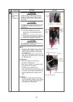
3) Remove flange nut from the fan motor and
propeller fan.
4) Remove propeller fan.
5)
Remove inverter
box cover
from inverter box
(Ø4 × 8, 1 pcs.)
6) Remove the connector of fan motor from the
inverter box.
7)
Remove fan motor lead from the fan motor
lead fixing rubber at the partition plate.
8)
9)
For fan motor lead (Upper), Cut the white
binding band 1 pcs.
and remove fan motor
lead from core clamp on
Inverter
box
.
For fan motor lead (Lower), Remove them
from Cable clamp 2 position.
10)
Cut the binding band at base motor.
11)
Loose the 3 claws (Each motor) on the
base
motor.
12)
Remove the fixing screws (4 Positions / each)
while holding the fan motor so as not to fall it.
Loosened by
turning clockwise
Propeller fan
Flange nut
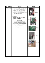
Connector of fan motor (Upper)
Connector of fan motor (Lower)
Screw
Cover inverter
- 96 -

