– 105 –
No. Part name
Procedure
Remarks
g
Electrical
part
replacement
(continued)
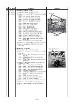
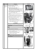
5. Indoor unit reactor
1) Following to work of item to 2) of 1 of
g
.
2) Remove the connecter of the reactor lead wire
connected to the reactor.
3) Remove the fixing screws of the reactor. (2 pcs Ø4×8)
4) Attach a new reactor to the inverter box.
6. FAN-IPDU board reactor
1) Following to work of item to 2) of 1 of
g
.
2) Remove the wires connected to the PTC thermistor.
3) Remove the fixing screws of the PTC thermistor.
(2 pcs, Ø4 × 12)
4) Attach the new reactor to the inverter box.
7. Reactor (CH90)
1) Following to work of item to 2) of 1 of
g
.
2) Following to work of item
f
.
3) Remove the lead wires attached to CN09 and CN10 of
the A3-IPDU P.C. board.
4) Remove the fixing screws of the reactor.
(2 pcs, Ø4 × 8)
5) Attach a new reactor in the inverter box.
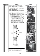
8. Power relay
1) Following to work of item to 2) of 1 of
g
.
2) Remove the fixing screws of the lead wires connected
to the power relay.
3) Remove the power relay. (2 pcs, Ø4 × 12)
4) Attach the new power relay to the inverter box.
9. PTC thermistor
1) Following to work of item to 2) of 1 of
g
.
2) Remove the lead wires connected to the PTC
thermistor.
3) Remove the fixing screws of the PTC thermistor.
(2 pcs, Ø4 × 12)
4) Attach the new PTC thermistor to the inverter box.
Indoor unit reactor (CH68)
FAN-IPDU board reactor (CH85)
Reactor (CH90)
PTC thermistor
Power relay


