background image

– 16 –


„

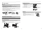
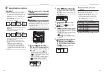
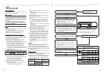
Wiring between indoor unit and outdoor unit

1. Figure below shows the wiring connections between the indoor and outdoor units and between the indoor units 

and remote controller. The wires indicated by the broken lines or dot-and-dash lines are provided at the locally.

2. Refer to the both indoor and outdoor unit wiring diagrams.
3. The power of the indoor unit is supplied from the outdoor unit.

Wiring diagram

Single system

Remote controller 

Remote controller wiring

Indoor side

System interconnection wires

Outdoor side

A B

1

1

2

2

3

3

Power supply

Simultaneous twin system

Remote controller 

Remote controller wiring

Indoor side

System interconnection wires

Outdoor side

A B

1

2

3

A B

1

1

2

2

3

3

Power supply

Indoor 

side

Indoor power 

inter-unit wiring

Remote controller 

inter-unit wiring

Simultaneous triple and double twin system

Remote controller 

Remote controller 

wiring

Indoor side

System interconnection 

wires

Outdoor side

A B

1

2

3

A B

1

2

3

A B

1

2

3

A B

1

2

3

1

2

3

Remote controller 

inter-unit wiring

Indoor power 

inter-unit wiring

Indoor power 

inter-unit wiring

Triple

Double twin

Indoor power 

inter-unit wiring

Power supply

Indoor side

Indoor side

Indoor side

Remote controller 

inter-unit wiring

Remote controller 

inter-unit wiring

*    Use 2-core shield wire (MVVS 0.5 to 2.0 mm

2

 or more) for the remote controller wiring in the simultaneous triple 

and simultaneous double twin systems to prevent noise problems. Be sure to connect both ends of the shield 
wire to earth leads.

*    Connect earth wires for each indoor unit in the simultaneous twin, simultaneous triple and simultaneous double 

twin systems.


„

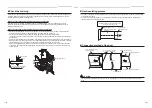
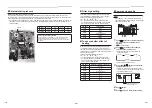
Wire connection

REQUIREMENT


y

Connect the wires matching the terminal numbers. Incorrect connection causes a trouble.


y

Pass the wires through the bushing of wire connection holes of the indoor unit.


y

Keep a margin (Approx. 100 mm) on a wire to hang down the electrical control box at servicing or other purpose.


y

The low-voltage circuit is provided for the remote controller. (Do not connect the high-voltage circuit)


y

Before performing wiring work in the electrical control box, remove the 
air 

fi

lter and the cover of the box (

fi

xed with 2 screws).


y

Remove screw A, and loosen screw B.


y

Pull up and open the electrical control box cover.


y

Tighten the screws of the terminal block 

fi

rmly, and 

fi

x the wires with 

the cord clamps attached to the electrical control box. (Do not apply 
tension to the connecting section of the terminal block.)


y

Slide the electrical control box cover to install it. Do not pinch the wire 
and make the gap as small as possible when installing the cover.

Electrical control 

box cover

Loosen screw B

Remove screw A

1

3

10

30

10

50

2

Side D (Space: 8.5 mm)

Side C (Space: 4 mm)

Cord clamp

Remote controller 
wiring

Earth screw

Earth wire

System interconnection 
wire

System interconnection wire

System interconnection wire

See the 

fi

gure on the left for 

system interconnection wires to 

the terminal block.

2 mm or 

less

Select side C or D for the power cable clamping position referring 

to the following table according to the cable type and diameter.

* Cable clamp can be attached on either right or left side.

When twin system are connected, clamp two cables with one 

cable clamp.

Wire type

Speci

fi

 cation

Cable clamping position

Cabtyre cable

4-core stranded wire 2.5 mm²

Side D

Cabtyre cable

4-core stranded wire 1.5 mm²

Side C


„

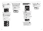
Remote controller wiring

Strip off approx. 9 mm the wire to be connected.

Wiring diagram

A
B

A
B

Terminal block for remote 

controller wiring of indoor unit

Remote controller wire 

(Locally procured)

Terminal block

Remote 

controller 

unit

32-EN

31-EN

Summary of Contents for RAV-GM901BTP-E

Page 1: ...AIR CONDITIONER SPLIT TYPE Installation Manual Indoor Unit Model name Concealed Duct Type RAV GM901BTP E For commercial use English ...

Page 2: ...ainted with the knowledge related to this work The qualified installer who is allowed to do the refrigerant handling and piping work involved in installation relocation and removal has the qualifications pertaining to this refrigerant handling and piping work as stipulated by the local laws and regulations and he or she is a person who has been trained in matters relating to refrigerant handling a...

Page 3: ...hich leave aftereffect and require hospitalization or long term treatment as an outpatient 2 Slight injury indicates injury burns electric shock and other injuries which do not require hospitalization or long term treatment as an outpatient 3 Damage to property indicates damage extending to buildings household effects domestic livestock and pets MEANINGS OF SYMBOLS DISPLAYED ON THE UNIT WARNING Ri...

Page 4: ...rotective gloves and safety work clothing during installation servicing and removal Do not touch the aluminum fin of the outdoor unit You may injure yourself if you do so If the fin must be touched for some reason first put on protective gloves and safety work clothing and then proceed Before opening the suction board cover set the circuit breaker to the OFF position Failure to set the circuit bre...

Page 5: ...ilure to follow these instructions may cause the product to fall down or topple over or give rise to noise vibration water leakage or other trouble Carry out the specified installation work to guard against the possibility of high winds and earthquake If the air conditioner is not installed appropriately a unit may topple over or fall down causing an accident If refrigerant gas has leaked during t...

Page 6: ... be easily accessed by the agent When installing the circuit breaker outdoors install one which is designed to be used outdoors Under no circumstances the power wire must not be extended Connection trouble in the places where the wire is extended may give rise to smoking and or a fire Electrical wiring work shall be conducted according to law and regulation in the community and installation manual...

Page 7: ...ith the service valve left open and the compressor still operating will cause air or other gas to be sucked in raising the pressure inside the refrigeration cycle to an abnormally high level and possibly resulting in rupture injury or other trouble CAUTION This Air Conditioner has adopted a refrigerant HFC R32 which does not destroy the ozone layer As the R32 refrigerant is easily affected by impu...

Page 8: ...the plastic parts to be damaged and other such problems to result y Locations near obstructions such as ventilation openings or lighting fixtures where the flow of the blown air will be disrupted a disruption of the air flow may cause the air conditioner s performance to deteriorate or the unit to shut down y Locations where an in house power generator is used for the power supply The power line f...

Page 9: ... cleaning of the remote controller can be changed according to the condition of installation For setup method refer to Filter sign setting in the Applicable controls of this Manual CAUTION Strictly comply with the following rules to prevent damage of the indoor units and human injury y Do not put a heavy article on the indoor unit or let a person get on it Even units are packaged y Carry in the in...

Page 10: ...ceiling correctly in order to prevent vibration of ceiling board y Attach the nuts and the M10 flat washers to the hanging bolt y Put washers at up and down of the hanging bracket of the indoor unit to hang down the indoor unit y Check that four sides are horizontal with a level gauge Horizontal degree Within 5 mm M10 flat washer M10 flat washer Hanging bolt W3 8 or M10 Nut W3 8 or M10 Nut W3 8 or...

Page 11: ...ing materials for piping work and insulating process are locally procured Pipe material Hard vinyl chloride pipe VP25 Nominal outer diameter Ø32 mm Insulator Foamed polyethylene foam thickness 10 mm or more Connecting drain pipe Insert flexible drain hose into the drain pipe of main unit as far as it will go Fix it with hose band REQUIREMENT Mount the flexible drain hose using the hose band withou...

Page 12: ...lly starts running Check whether the water is draining from the drain pipe connecting port and check that no water is leaking from the drain pipe After checking that the water drains and there are no water leaks turn off the power connect the float switch connector to its original location CN34 on the printed circuit board and return the electrical control box to its original position Supply water...

Page 13: ...00 1500 1600 1700 1800 1900 2000 2100 2200 Air volume m3 h External static pressure Pa Standard filter pressure loss Upper limit of external static pressure 120 Pa Lower limit of external static pressure 120 Pa High tap 120 Pa High tap 100 Pa High tap 80 Pa High tap 65 Pa High tap 50 Pa High tap 40 Pa High tap 30 Pa Low tap 30 Pa Low tap 120 Pa 24 EN 23 EN ...

Page 14: ...duct at the local site 254 27 27 37 5 37 5 1359 4 100 100 235 4 100 100 100 100 100 100 100 100 100 100 100 100 100 254 1375 27 27 37 5 37 5 1360 235 2 100 100 100 100 100 100 100 100 100 100 100 100 100 100 100 GM90 Under air intake Back air intake 6 Duct design 26 EN 25 EN ...

Page 15: ...ze The copper pipe gauge is useful for adjusting projection margin size y The sealed gas was sealed at the atmospheric pressure so when the flare nut is removed there will no whooshing sound This is normal and is not indicative of trouble y Use two wrenches to connect the indoor unit pipe Work using double spanner y Use the tightening torque levels as listed in the following table Outer dia of con...

Page 16: ...hortage of power circuit or incomplete installation may cause an electric shock or a fire CAUTION y For power supply specifications follow the Installation Manual of outdoor unit y Do not connect 220 240V power to the terminal blocks A B for control wiring Otherwise the system will fail Do not damage or scratch the conductive core and inner insulator of power and system interconnection wires when ...

Page 17: ...ncorrect connection causes a trouble y Pass the wires through the bushing of wire connection holes of the indoor unit y Keep a margin Approx 100 mm on a wire to hang down the electrical control box at servicing or other purpose y The low voltage circuit is provided for the remote controller Do not connect the high voltage circuit y Before performing wiring work in the electrical control box remove...

Page 18: ...x 1 minutes y Normal settings were made when the indoor unit was shipped from factory Change the indoor unit settings as required y Use the wired remote controller to change the settings The settings cannot be changed using the wireless remote controller sub remote controller or remote controller less system for central remote controller only Therefore install the wired remote controller to change...

Page 19: ...50 H 0002 2500 H Factory default 0003 5000 H 0004 10000 H To secure better effect of heating When it is difficult to obtain satisfactory heating due to installation place of the indoor unit or structure of the room the detection temperature of heating can be raised Also use a circulator or other device to circulate heat air near the ceiling Follow to the basic operation procedure 1 2 3 4 5 6 y For...

Page 20: ... TE 61 Outside air temperature TO 62 Compressor discharge temperature TD 63 Compressor suction temperature TS 64 65 Heatsink temperature THS 6A Operating current x1 10 F1 Compressor cumulative operating hours x100 h Group control Simultaneous twin triple or double twin system A combination with an outdoor unit allows simultaneous ON OFF operation of the indoor units The following system patterns a...

Page 21: ...ddress Indoor No After setup of automatic address Example of random setup Procedure example 1 After setup change of manual address Line system Indoor unit Indoor unit Indoor unit Indoor unit Indoor unit Remote controller Twin system Single system Triple system The above address is set by the automatic addressing when the power is turned on However line addresses and indoor addresses are set random...

Page 22: ... be again set up Therefore repeat procedure of the setup change from the Procedure 1 To recognize the position of the corresponding indoor unit though the indoor UNIT No is known Check the position during operation stop Stop operation of the unit 2 1 3 1 1 Push buttons simultaneously for 4 seconds or more After a while the display part flashes and the display appears as shown below In this time th...

Page 23: ...the power supply carry out the following procedure 1 By using 500V megger check that resistance of 1 MΩ or more exists between the terminal block 1 to 3 and the earth grounding If resistance of less than 1 MΩ is detected do not run the unit 2 Check the valve of the outdoor unit being opened fully y To protect the compressor at activation time leave power ON for 12 hours or more before operating Ex...

Page 24: ...oor units in test run TEMPORARY button 11 Maintenance Daily maintenance 4 Cleaning of the air filter If is displayed on the remote controller maintain the air filter 3 1 2 1 Push the button to stop the operation then turn off the circuit breaker After the cooling or dry operation the fan keeps running for self cleaning Push the button twice to stop the operation 1 Take out the air filter y Slide a...

Page 25: ...rmal sound is generated Filter Indoor Dust dirt breakage y Wash the filter with water when it is contaminated y Replace it when it is damaged Fan Indoor y Vibration balance y Dust dirt appearance y Replace the fan when vibration or balance is terrible y Brush or wash the fan when it is contaminated Air intake discharge grilles Indoor outdoor Dust dirt scratches Fix or replace them when they are de...

Page 26: ...op F13 ALT Heat sink sensor error Outdoor Abnormal temperature was detected by the temp sensor of the IGBT heat sink Entire stop Wired remote controller display Wireless remote controller Sensor block display of receiving unit Main problem parts Judging device Parts to be checked error description Air conditioner status Indication Operation Timer Ready GR GR OR Flashing F15 ALT Temp sensor connect...

Page 27: ...rs TC TCJ An error was detected due to temperature drop of the indoor unit heat exchanger sensor when heating Auto reset P20 ALT High pressure protective operation Outdoor High pressure protection Entire stop P22 ALT Outdoor unit fan error Outdoor Outdoor unit fan motor outdoor unit P C board An error overcurrent locking etc was detected in the outdoor unit fan drive circuit Entire stop P26 ALT Ou...

Page 28: ... works 2 When the existing pipe thickness is thinner than the specified Pipe diameter and thickness be sure to use new pipes for the refrigerant piping works y The operating pressure of refrigerant is high If there is a scratch or dent on the pipe or a thinner pipe is used the pressure strength may be inadequate which may cause the pipe to break in the worst case Pipe diameter and thickness mm Pip...

Page 29: ... 28 56 EN 55 EN ...
Page 30: ...1116950190 144 9 Moo 5 Bangkadi Industrial Park Tivanon Road Tambol Bangkadi Amphur Muang Pathumthani 12000 Thailand ...

Reviews: