- 89 -
EN-177
EN-178
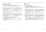
How to check the existing piping settings
You can check whether the existing piping settings are enabled.
1.
Check that the LED displays are placed in their initial status. If not, place them in the initial status.
2.
Hold down SW01 for at least 5 seconds, and check that D804 flashes slowly. (Fig. 9)
3.
Press SW01 four times to set the LED displays (D800 to D805) to the “LED displays for existing piping settings”
shown below. If the setting is enabled, D802 lights and D804 and D805 flash rapidly. (Fig. 10)
4.
Hold down SW01 and SW02 simultaneously for at least 5 seconds to return the LED displays to the initial status.
:ON, :OFF, :Slow
flashing
:ON, :OFF, :Rapid
flashing
When restoring the factory defaults
To restore the factory defaults in situations such as when relocating the units, follow the steps below.
1.
Check that the LED displays are placed in their initial status. If not, place them in the initial status.
2.
Hold down SW01 for at least 5 seconds, and check that D804 flashes slowly. (Fig. 11)
3.
Press SW01 20 times to set the LED displays (D800 to D805) to the “LED displays restored to factory defaults”
shown below. (Fig. 12)
:ON, :OFF, :Slow
flashing
:ON, :OFF, :Rapid
flashing
4.
Hold down SW02 for at least 5 seconds, and check that D804 flashes slowly. (Fig. 13)
5.
Hold down SW01 and SW02 simultaneously for at least 5 seconds to return the LED displays to the initial status.
:ON, :OFF, :Slow
flashing
(Fig. 9)
LED displays indicated when step 3 is taken
D800
D801
D802
D803
D804
D805
(Fig. 10)
LED displays for existing piping settings
D800
D801
D802
D803
D804
D805
(Fig. 11)
LED displays indicated when step 2 is taken
D800
D801
D802
D803
D804
D805
(Fig. 12)
LED displays restored to factory defaults
D800
D801
D802
D803
D804
D805
(Fig. 13)
LED displays indicated when step 4 is taken
D800
D801
D802
D803
D804
D805
14
TROUBLESHOOTING
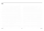
You can perform fault diagnosis of the outdoor unit with the LEDs on the P.C. board of the outdoor unit in addition to
using the check codes displayed on the wired remote controller of the indoor unit.
Use the LEDs and check codes for various checks. Details of the check codes displayed on the wired remote
controller of the indoor unit are described in the Installation Manual of the indoor unit.
LED Displays and Check Codes
···ON
···OFF
···Rapid flashing (5 times/sec)
No.
Trouble description
LED display
D800 D801 D802 D803 D804 D805
1 Normal
2 Discharge temp. sensor (TD) trouble
3
Heat exchanger temp. sensor (TE)
trouble
4
Heat exchanger temp. sensor (TL)
trouble
5
Outside air temp. sensor (TO)
trouble
6 Suction temp. sensor (TS) trouble
7 Heat sink temp. sensor (TH) trouble
8 Miss-mounting of sensor (TE, TS)
9 EEPROM trouble
10 Compressor break down
11 Compressor lock
12 Current detection circuit trouble
13 Case thermostat operation
14 Unset model type of P.C.board
15 MCU communication trouble
16 Discharge temp. trouble
17 High pressure SW operation
18 Power supply trouble
19 Heat sink overheat trouble
20 Gas leak detection
21 4-way valve inverse trouble
22 High pressure protective operation
23 Fan system trouble
24
Short-circuit of compressor drive
element
25 Position detection circuit trouble
SW02
SW01
LED
(D800 to D805)
<GP110, GP140>
<GP80>
SW02
SW01
LED
(D800 to D805)
Summary of Contents for RAV-GP1101AT-E
Page 95: ... 94 MEMO EN 187 EN 188 ...
Page 96: ...EB99845801 ...

