background image

– 13 –

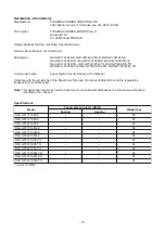
Declaration of Conformity

Manufacturer:

TOSHIBA CARRIER CORPORATION

336 Tadehara, Fuji-shi, Shizuoka-ken 416-8521 JAPAN

TCF holder:

TOSHIBA CARRIER EUROPE S.A.S

Route de Thil

01120 Montluel FRANCE

Hereby declares that the machinery described below:

Generic Denomination: Air Conditioner

Model/type:

RAV-GP1101AT8-E, RAV-GP1401AT8-E, RAV-GP1601AT8-E

RAV-GP1101AT8J-E, RAV-GP1401AT8J-E, RAV-GP1601AT8J-E

RAV-GP1101AT8-TR, RAV-GP1401AT8-TR, RAV-GP1601AT8-TR

RAV-GP1101AT8J-TR, RAV-GP1401AT8J-TR, RAV-GP1601AT8J-TR

Commercial name:

Super Digital Inverter Series Air Conditioner

Complies with the provisions of the “Machinery Directive” (Directive 2006/42/EC) and the regulations

transposing into national law

Note: 

This declaration becomes invalid if technical or operational modifications are introduced without the

manufacturer’s consent.

Specifications

Model

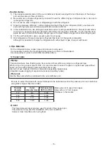
 Under 70 dB(A)

Sound pressure level (dB(A))

Weight (kg)

Cooling

RAV-GP1101AT8-E

RAV-GP1401AT8-E

RAV-GP1601AT8-E

RAV-GP1101AT8J-E

RAV-GP1401AT8J-E

RAV-GP1601AT8J-E

RAV-GP1101AT8-TR

RAV-GP1401AT8-TR

RAV-GP1601AT8-TR

RAV-GP1101AT8J-TR

RAV-GP1401AT8J-TR

RAV-GP1601AT8J-TR


Heating


95

95

95

95

95

95

95

95

95

95

95

95
Summary of Contents for RAV-GP1101AT8-E

Page 1: ...019 SERVICE MANUAL AIR CONDITIONER SPLIT TYPE OUTDOOR UNIT SUPER DIGITAL INVERTER RAV GP1101AT8 E RAV GP1101AT8 TR RAV GP1101AT8J E RAV GP1101AT8J TR RAV GP1401AT8 E RAV GP1401AT8 TR RAV GP1401AT8J E RAV GP1401AT8J TR RAV GP1601AT8 E RAV GP1601AT8 TR RAV GP1601AT8J E RAV GP1601AT8J TR ...

Page 2: ...407C 32 6 6 1 Basic Conditions Needed to Reuse the Existing Pipe 32 6 6 2 Restricted Items to Use the Existing Pipes 32 6 6 3 Branching Pipe for Simultaneous Operation System 32 6 6 4 Curing of Pipes 32 6 6 5 Final Installation Checks 33 6 6 6 Handling of Existing Pipe 34 6 6 7 Recovering Refrigerant 34 6 7 Charging additional refrigerant 34 6 7 1 Assumed gas leak 34 6 7 2 Limiting the additional ...

Page 3: ...oup Control 80 10 2 1 System Configuration 81 10 2 2 Automatic Address Example from Unset Address No miss wiring 82 10 3 Remote Controller Wiring 83 10 4 Address Setup Manual setting from remote controller 84 10 5 Confirmation of Indoor Unit No Position 85 11 REPLACEMENT OF THE SERVICE P C BOARD MCC 1599 87 12 HOW TO EXCHANGE COMPRESSOR 88 12 1 Exchanging Procedure of Compressor Outline 88 12 2 Ex...

Page 4: ...een instructed in such matters by an individual or individuals who have been trained and is thus thoroughly acquainted with the knowledge related to this work The qualified installer that is allowed to work at heights has been trained in matters relating to working at heights with the air conditioners made by Toshiba Carrier Corporation or alternatively he or she has been instructed in such matter...

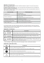
Page 5: ... provide protection for electricians Insulating shoes Clothing to provide protection from electric shock Helmets for use in industry Shoes with additional protective toecap Gloves to provide protection for electricians Indication DANGER WARNING CAUTION Explanation Indicates contents assumed that an imminent danger causing a death or serious injury of the repair engineers and the third parties when...

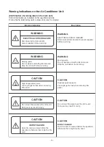
Page 6: ...get burned when removing this panel CAUTION Do not touch the aluminum fins of the unit Doing so may result in injury CAUTION BURST HAZARD Open the service valves before the operation otherwise there might be the burst Description WARNING ELECTRICAL SHOCK HAZARD Disconnect all remote electric power supplies before servicing WARNING Moving parts Do not operate unit with grille removed Stop the unit ...

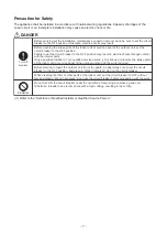
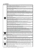
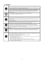
Page 7: ...the interior parts Only a qualified installer 1 or qualified service person 1 is allowed to remove the intake grille of the indoor unit or service panel of the outdoor unit and do the work required Bef Do not turn ON the circuit breaker under the condition of removing a cabinet a panel etc Otherwise it leads to an electric shock with a high voltage resulting in loss of life ore starting to repair ...

Page 8: ...imb onto or place objects on top of the outdoor unit You may fall or the objects may fall off the outdoor unit and result in injury When transporting the air conditioner wear shoes with additional protective toecap When transporting the air conditioner do not hold the bands around the packing carton You may injure yourself if the bands should break This air conditioner has passed the pressure test...

Page 9: ...omes absolutely necessary to check out the electrical parts with the electrical parts box cover of one or more of the indoor units and the service panel of the outdoor unit removed in order to find out exactly where the trouble lies place Keep out signs around the work site before proceeding Third party individuals may enter the work site and receive electric shocks if this warning is not heeded C...

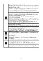
Page 10: ...d with the refrigerant abnormal high pressure generates in the refrigerating cycle resulted in cause of injury due to breakage After the installation work confirm that refrigerant gas does not leak If refrigerant gas leaks into the room and flows near a fire source such as a cooking range noxious gas may be generated Never recover the refrigerant into the outdoor unit When the equipment is moved o...

Page 11: ...has been shut down set the circuit breaker to the OFF position and then wait at least 10 minutes before opening the service panel If you fail to heed this warning you will run the risk of burning yourself because the compressor pipes and other parts will be very hot to the touch In addition before proceeding with the repair work wear the kind of insulated heat resistant gloves designed to protect ...

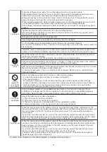
Page 12: ...he law in the local regulations and laws Install the circuit breaker where it can be easily accessed by the agent Do not place any combustion appliance in a place where it is directly exposed to the wind of air conditioner otherwise it may cause imperfect combustion Prohibition CAUTION Wearing of gloves Ensure wearing of gloves when performing any work in order to avoid injury from parts etc Failu...

Page 13: ...01AT8J TR RAV GP1601AT8J TR Commercial name Super Digital Inverter Series Air Conditioner Complies with the provisions of the Machinery Directive Directive 2006 42 EC and the regulations transposing into national law Note This declaration becomes invalid if technical or operational modifications are introduced without the manufacturer s consent Specifications Model Under 70 dB A Sound pressure lev...

Page 14: ...re to check for leakage refrigerant or residual refrigerant If the leakage refrigerant comes into contact with fire a poisonous gas may occur or it may cause a fire Keep adequate ventilation during the work 4 When refrigerant gas leaks during work execute ventilation If the leakage refrigerant comes into contact with a fire a poisonous gas may occur or it may cause a fire 5 In places where install...

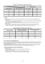
Page 15: ...as charge it with liquid 3 Pipe Materials For the refrigerant pipes copper pipe and joints are mainly used It is necessary to select the most appropriate pipes to conform to the standard Use clean pipes or joints to which little impurities adhere 1 Copper pipe Be sure to select the pipes with copper thickness in the table below since the pressure of an air conditioner using R32 is higher than that...

Page 16: ...amage of the equipment but also a fire etc R410A tools available Partly unavailable R410A tools unavailable No Installation service tools Tools Equipment specification 1 Flare tool Clutch type Pipe flaring Use Applicability to R32 air conditioner or not Applicability to R22 air conditioner or not 5 Charge hose High voltage 3 Torque wrench Tightening of flare nut 6 Vacuum pump Vacuum drying Note 3 ...

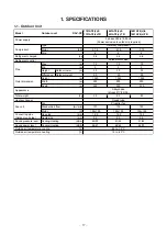
Page 17: ...1 0 0 1 0 0 1 0 0 1 0 0 1 0 0 1 W r o t o M 9 5 1 9 5 1 9 5 1 m m e d i s s a G e p i p g n i t c e n n o C Outdoor unit side Liquid side mm 9 5 9 5 9 5 Sound pressure level Cooling Heating dB A 49 50 51 52 51 53 Sound power level Cooling Heating dB A 66 67 68 69 68 70 C g n i l o o c e r u t a r e p m e t r i a e d i s t u O C g n i t a e h e r u t a r e p m e t r i a e d i s t u O Pipe Outdoor u...

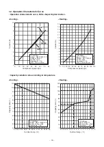
Page 18: ...eed rps Conditions Indoor DB27 C WB19 C Outdoor DB35 C Air flow High Pipe length 7 5m 400V 50Hz 3 phase Conditions Indoor DB20 C Outdoor DB7 C WB6 C Air flow High Pipe length 7 5m 400V 50Hz 3 phase SP160 SP160 GP140 GP110 GP160 50 55 60 65 70 75 80 85 90 95 100 105 32 33 34 35 36 37 38 39 40 41 42 43 44 45 46 Outdoor temp C Capacity ratio 0 10 20 30 40 50 60 70 80 90 100 110 120 14 16 18 20 12 10 ...

Page 19: ... 19 2 CONSTRUCTION VIEWS EXTERNAL VIEWS 2 1 Outdoor Unit RAV GP1101AT8 J E TR RAV GP1401AT8 J E TR RAV GP1601AT8 J E TR ...

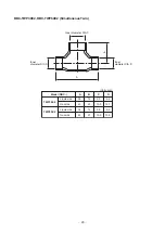
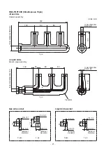
Page 20: ...Simultaneous Twin Inner diameter DIA C Inner diameter DIA D Units mm Inner diameter DIA D A B Model RBC TWP30E2 Liquid side Gas side TWP50E2 Liquid side Gas side A B C D 36 43 34 44 14 23 14 21 9 5 15 9 9 5 15 9 6 4 12 7 9 5 15 9 ...

Page 21: ...rnal diameter Inner diameter DIA 25 4 Inner diameter DIA 12 7 Inner diameter DIA 15 9 Inner diameter DIA 9 52 Insulator 300 80 80 100 80 80 100 DIA 12 7 DIA 6 4 DIA 9 5 100 28 10 24 8 26 9 100 35 3 pcs 3 pcs 1 pc 1 pc 1 pc DIA 25 4 External diameter DIA 15 9 46 12 1 pc Liquid side Branch pipe assembly Gas side socket Liquid side socket ...

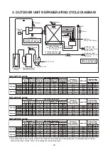
Page 22: ... 3 0 19 0 23 0 36 6 35 4 33 0 40 2 26 4 90 6 HIGH HIGH LOW HIGH LOW HIGH 27 19 32 24 18 15 5 20 30 15 35 46 15 7 6 24 18 20 RAV GP1401 series Pressure Pipe surface temperature Compressor drive revolution frequency rps Indoor fan Indoor outdoor temp condition Mpa kg cm2G Discharge Suction Indoor heat exchanger Outdoor heat exchanger Pd Ps Pd Ps TD TS TC TL TE Indoor Outdoor Heating Cooling Standard...

Page 23: ... 23 4 WIRING DIAGRAM 4 1 Outdoor Unit RAV GP1101AT8 J E TR RAV GP1401AT8 J E TR RAV GP1601AT8 J E TR ...

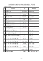
Page 24: ...board MCC 1596 Fuse Mounted on P C board MCC 1597 Fuse Mounted on P C board MCC 1597 Fuse Mounted on P C board MCC 1599 Fuse Mounted on P C board MCC 1600 Relay Posistor Compressor thermostat Type RX420A3F 27M ICF 280 A100 1 STF H01AJ1736A1 UKV A038 ACB 4UB83W CH 78 CH 68 CH 56 MCC 1596 MCC 1597 MCC 1599 MCC 1600 TLC 10A GAC1 31 5A SCT 3 15A GDM 250V 15A SCT 3 15A FJL 250V 3 15A ET 6 3A EL200 240A...

Page 25: ...ration cycle may become abnormally high so that a rupture or personal injury may be caused 5 After completion of installation work check to make sure that there is no refrigeration gas leakage If the refrigerant gas leaks into the room coming into contact with fire in the fan driven heater space heater etc a poisonous gas may occur 6 When an air conditioning system charged with a large volume of r...

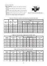
Page 26: ...imum thicknesses of socket joints Nominal diameter 1 4 3 8 1 2 5 8 Reference outer diameter of copper pipe jointed mm 6 4 9 5 12 7 15 9 Minimum joint thickness mm 0 50 0 60 0 70 0 80 6 2 2 Processing of Piping Materials When performing the refrigerant piping installation care should be taken to ensure that water or dust does not enter the pipe interior that no other oil other than lubricating oils...

Page 27: ...kness mm 0 8 0 8 0 8 1 0 1 0 Dimension mm A B C D 9 1 9 2 6 5 13 13 0 13 5 9 7 20 16 2 16 0 12 9 20 19 4 19 0 16 0 23 23 3 24 0 19 2 34 Flare nut width mm 17 22 24 27 36 Nominal diameter 1 4 3 8 1 2 5 8 3 4 Outer diameter mm 6 4 9 5 12 7 15 9 19 1 Thickness mm 0 8 0 8 0 8 1 0 1 2 Dimension mm A B C D 9 1 9 2 6 5 13 13 2 13 5 9 7 20 16 6 16 0 12 9 23 19 7 19 0 16 0 25 24 0 19 2 28 Flare nut width m...

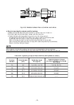
Page 28: ...es designated by manufacturers Table 6 2 6 shows reference values NOTE When applying oil to the flare surface be sure to use oil designated by the manufacturer If any other oil is used the lubricating oils may deteriorate and cause the compressor to burn out 43 to 45 45 to 46 A B C D Fig 6 2 2 Relations between flare nut and flare seal surface Table 6 2 6 Tightening torque of flare for R410A or R3...

Page 29: ...to 2 minutes and ensure that the compound gauge s pointer does not return Set the refrigerant cylinder to the electronic balance connect the connecting hose to the cylinder and the connecting port of the electronic balance and charge liquid refrigerant INDOOR unit Liquid side Refrigerant cylinder With siphon pipe Check valve Gas side Open Close valve for charging Electronic balance for refrigerant...

Page 30: ...pper alloy and is relatively expensive though it excels in solder ability 2 Phosphor bronze brazing filler Phosphor bronze brazing filler is generally used to join copper or copper alloy 3 Low temperature brazing filler Low temperature brazing filler is generally called solder and is an alloy of tin and lead Since it is weak in adhesive strength do not use it for refrigerant pipes 1 Phosphor bronz...

Page 31: ...ine contained in the flux remains within the pipe the lubricating oil deteriorates Therefore use a flux which does not contain chlorine 3 When adding water to the flux use water which does not contain chlorine e g distilled water or ion exchange water 4 Remove the flux after brazing 6 5 3 Brazing As brazing work requires sophisticated techniques experiences based upon a theoretical knowledge it mu...

Page 32: ...pper green rust generated 6 Check the oil when the existing air conditioner was removed after refrigerant had been recovered In this case if the oil is judged as clearly different compared with normal oil The refrigerator oil is copper rust green There is possibility that moisture is mixed with the oil and rust forms inside of the pipe There is discolored oil a large quantity of the remains or bad...

Page 33: ...pprox 30 minutes or longer recover the refrigerant For cleaning the pipes and recovering oil Refrigerant recovery Pump down method Connect the indoor outdoor units to the existing pipe Use a flare nut attached indoor outdoor units Do not existing pipe Re machine the flare machining size to size for R32 Airtight test Vacuum dry Refrigerant charge Gas leak check Was largely discolored oil or a large...

Page 34: ...7 Recovering Refrigerant Use the refrigerant recovery equipment to recover the refrigerant 6 7 Charging additional refrigerant Amount of additional refrigerant shall be restricted by the following explanation to ensure the reliability Miss charging leads to the abnormal high pressure in the refrigerant cycle causing a rupture an injury and a compressor malfunction 6 7 1 Assumed gas leak The refrig...

Page 35: ...d to accelerate this process When oil is drained from a system it shall be carried out safely 6 8 2 Decommissioning Before carrying out this procedure it is essential that the technician is completely familiar with the equipment and all its details Only a qualified installer 1 or qualified service person 1 is allowed to do this work It is recommended good practice that all refrigerants are recover...

Page 36: ...e Connector for MCC 1597 CN502 CN13 Black Terminal for power relay F02 Electric circuit protective fuse 500V 31 5A CN12 White Terminal for MCC 1600 CN17 F01 Electric circuit protective fuse 500V 31 5A CN11 Red Terminal for power relay CN04 Red Terminal for PTC thermistor CN19 Yellow CN20 Yellow Terminal for reactor CH78 CN211 Red CN212 White CN213 Black Compressor output terminal ...

Page 37: ... for MCC 1599 CN802 CN602 Black Connector for MCC 1600 CN51 F500 Electric circuit protective fuse 250V 15A P501 Black Lead wire for grounding CN505 Red Connector for MCC 1596 CN851 CN502 White Connector for MCC 1596 CN101 CN700 Blue Fan motor output Lower side CN500 Red Connector for MCC 1600 CN23 and reactor CH68 ...

Page 38: ... Red Connector for MCC 1600 CN10 and CN19 CN802 White Connector for MCC 1597 CN504 CN708 Blue Connector for power relay coil CN608 White Connector for MCC 1600 CN50 Temp sensor connector CN604 White TL sensor CN603 White TD sensor CN602 Yellow TO sensor CN601 White TE sensor CN600 White TS sensor Specific operation switch SW801 SW804 SW805 SW806 Display select switch SW800 SW803 Initial setting sw...

Page 39: ...tor protective fuse 250V 6 3A CN07 Black Power supply terminal L3 F03 Varistor protective fuse 250V 6 3A CN20 White Power supply terminal L2 CN08 Gray Neutral terminal CN10 Red Terminal for MCC 1599 CN02 and Terminal for PTC thermistor CN16 Red Terminal for power relay CN17 White Terminal for MCC 1596 CN02 CN18 Black Terminal for power relay CN19 Gray Terminal for MCC 1599 CN02 CN09 Brown Terminal...

Page 40: ...s no trouble in the resistance value or the refrigerating cycle of each sensor after repair and then start the operation 2 Discharge temperature release control 1 When the discharge temperature did not fall or the discharge temperature rapidly went up by PMV control this control lowers the operation frequency It subdivides the frequency control up to 0 6Hz to stabilize the cycle 2 When the dischar...

Page 41: ... WD WD WD Temp range 10 C TO 5 C TO 10 C 3 C TO 5 C 10 C TO 3 C TO 10 C TO trouble 20 Hz 20Hz 45Hz or lower to 45Hz or higher Max Max Max W7 W8 W9 W9 WA WA WA WA WC WC WC WC WD WD WD WD WD WD 3 1 Cooling fan control c The outdoor fan is controlled by TL sensor TO sensor and the operation frequency The outdoor fan is controlled by every 1 tap of DC fan control 14 taps d Only for 60 seconds after th...

Page 42: ...pted and left as it is for a long time 3 A judgment for electricity is performed by TD and TO sensors If TO sensor is trouble a backup control is automatically performed by TE sensor For a case of TO sensor trouble judge it with outdoor LED display 4 For every model the power is turned off when TD is 30 C or more REQUIREMENT While heating the winding wire by applying a current to it an abnormal so...

Page 43: ...estarts after 2 minutes 30 seconds setting 1 as a trouble count 3 When the trouble count 8 was found determine a trouble and restart operation is not performed 4 For the check code display contents confirm on the check code list 9 High pressure release control 1 The operation frequency is controlled to restrain abnormal rising of high pressure by TL sensor in cooling operation and TC sensor in hea...

Page 44: ...her for 3 seconds or continued 7 C TE 12 C for 1 minute The defrost operation also finishes when it continued for 10 minutes even if TE sensor temperature was 7 C or lower 3 After defrost operation was reset the compressor stopped for approx 40 seconds and then the heating operation starts The minimum TE value and To value between 10 and 15 minutes after heating operation has started are stored in...

Page 45: ...rmed from remote controller Is it being operated by the central control system Is an automatic address being set up When the power is turned on at the first time or when indoor unit address setting is changed the operation cannot be performed for maximum approx 5 minutes after power ON Is being carried out a test run by operation of the outdoor unit 5 LED for the indoor and outdoor communication d...

Page 46: ...ration Is it being operated by the central control system Is an automatic address being set up When the power is turned on at the first time or when indoor unit address setting is changed the operation cannot be performed for maximum approx 5 minutes after power ON Is a test run of the air conditioner being carried out 5 LED for the indoor and outdoor communication does not flash LED is placed on ...

Page 47: ...le Communication stop between receiving unit and indoor unit Duplicated indoor unit No Setup trouble Duplicated header units of remote controller Communication trouble between CPUs on indoor unit P C board Wire connection trouble between indoor units Indoor power OFF Communication stop between indoor header and follower or between header and follower indoor twin Miss wiring between indoor unit and...

Page 48: ...uble Temp sensor miss wiring TE TS Indoor EEPROM trouble Outdoor EEPROM trouble Compressor break down Outdoor compressor system trouble 1 Compressor lock Current detection circuit trouble Power supply outdoor P C board trouble Case thermostat worked Compressor overheat outdoor wiring trouble PS pressure sensor trouble Outdoor unit low pressure protective operation low pressure system trouble Dupli...

Page 49: ...Timer Ready Simultaneous flash Operation Timer Ready Alternate flash Check code Cause of trouble occurrence During test run Disagreement of cool heat Automatic cool heat setting to automatic cool heat prohibited model or setting of heating to cooling only model ...

Page 50: ...rature TD Compressor suction temperature TS Heat sink temperature THS Operation current 1 10 Outdoor heat exchanger Coil temperature TL Compressor operation frequency Outdoor fan revolution frequency Lower Outdoor fan revolution frequency Upper Compressor calculated operation time Unit C C C C C A C rps rpm rpm 100h 1 Push buttons simultaneously for 4 seconds to call the service monitor mode The s...

Page 51: ...nit Temp sensor TS trouble ALT Outdoor Open Short circuit of suction temp sensor was detected F13 Outdoor unit Temp sensor TH trouble ALT Outdoor Open Short circuit of heat sink temp sensor Board installed was detected F15 Outdoor unit Misconnection of temp sensor TE TS ALT Outdoor Misconnection of outdoor heat exchanger temp sensor and suction temp sensor was detected F07 Outdoor unit Temp sensor...

Page 52: ...m air temp TA was detected F01 Indoor unit Heat exchanger sensor TCJ trouble ALT Indoor Open Short circuit of heat exchanger TCJ was detected F02 Indoor unit Heat exchanger sensor TC trouble ALT Indoor Open Short circuit of heat exchanger TC was detected There are multiple communication adapters Network adapter There are multiple communication adapters on remote controller communication line By un...

Page 53: ...rouble is detected Displayed when trouble is detected Displayed when trouble is detected Displayed when trouble is detected Displayed when trouble is detected Displayed when trouble is detected Displayed when trouble is detected Displayed when trouble is detected Displayed when trouble is detected Displayed when trouble is detected Displayed when trouble is detected Displayed when trouble is detec...

Page 54: ... 1597 and also connection check between CN505 of MCC 1597 and CN851 of MCC 1596 F23 Ps sensor trouble Stop Displayed when trouble is detected 1 Check connection of Ps sensor connector 2 Check failure of Ps sensor 3 Check compressing power trouble of compressor 4 Check 4 way valve trouble 5 Check outdoor P C board trouble P07 Heat sink overheat trouble Heat sink temp sensor detected over specified ...

Page 55: ...PMV 5 Check clogging of heat exchanger in indoor outdoor units 6 Short circuit status of suction discharge air in outdoor unit 7 Check outdoor P C board trouble 8 Check fan system trouble Cause of air volume drop at indoor side 9 Check PMV opening status in indoor unit P03 Discharge temp trouble Discharge temp TD over specified value was detected Stop Displayed when trouble is detected 1 Check ref...

Page 56: ...nit wiring 2 Check remote controller 3 Check indoor power wiring 4 Check indoor P C board E02 Signal send trouble to indoor unit Detected by remote controller side Stop Automatic reset If central controller exists operation continues Displayed when trouble is detected Sending trouble of remote controller 1 Check sending circuit inside of remote controller Replace remote controller E09 There are mu...

Page 57: ...e occurrence is indicated Display 1 If pushing the button switch SW800 for 1 second under the above condition the yellow LED is displayed with flashing Display 2 When pushing SW800 for 1 second again the status returns to Display 1 The trouble contents can be confirmed by combining Display 1 and Display 2 Display 1 Display 2 No trouble Push SW800 Trouble occurred D805 Green D804 Yellow D803 Yellow...

Page 58: ...play 1 Display 2 Display 1 Display 2 Display 1 Display 2 Display 1 Display 2 Check and troubleshooting Item without special mention Indicates part of outdoor unit Discharge temp sensor TD trouble There is a possibility that it is one of the following trouble Confirm LED on outdoor P C board to judge which trouble it is Heat exchanger temp sensor TE trouble Heat exchanger temp sensor TL trouble Suc...

Page 59: ...r normal YES NO Is CN600 connection normal Is resistance value of TS sensor normal YES NO Correct sensor mounting Is mounting status of TE and TS sensors normal Is CN600 connection normal Is resistance value of TS sensor normal Is CN601 connection normal Is resistance value of TE sensor normal YES YES YES NO NO NO Correct connector Sensor trouble Replace Replace outdoor P C board MCC 1599 Correct ...

Page 60: ...pressor side Reactor lead Power supply lead YES YES YES NO NO NO H02 Display 1 Display 2 Compressor lock Check wire connection and correct it Correct power supply line Is compressor normal Is there no refrigerant stagnation Does PMV normally operate Is power supply voltage normal AC342 to 457V Is wire connection normal Compressor lead Board side Compressor side Reactor lead Power supply lead Compr...

Page 61: ...ouble position Recharge refrigerant Replace outdoor P C board MCC 1599 Correct connector Case thermostat trouble Replace Is valve fully opened Is PMV normal Is there no gas leak Is it not refrigerant shortage Is cooling heating operation available when short circuiting case thermostat Are CN609 connection and case thermostat normal YES YES YES YES YES NO NO NO NO Replace PMV NO Display 1 Display 2...

Page 62: ...eat sink temp sensor TH trouble EEPROM trouble Unset model type Heat sink overheat trouble Gas leak detection 4 way valve inverse trouble Communication trouble between MCU 1 Connection check between CN802 of MCC 1599 and CN504 of MCC 1597 and also connection check between CN505 of MCC 1597 and CN851 of MCC 1596 2 Replace outdoor P C board MCC 1596 MCC 1597 MCC 1599 Heat sink temp sensor TH trouble...

Page 63: ...arge amount adequate YES NO NO YES YES NO NO YES Connection of connectors Fan IPDU Fan motor Wiring Is circuit wiring normal Is there no fan breakage or coming off Is service valve fully opened Does cooling outdoor fan normally operate B Cooling operation B Cooling operation C Heating operation Does high pressure switch operate Are parts of high pressure switch normal Reset the power supply and th...

Page 64: ...o P20 column Are characteristics of TC and TCJ sensor resistance value normal Are connections of connectors capacitors and fan motor normal Heating operation Does the heating indoor fan normally operate Clogging by refrigerant overcharge Pipe breakage Abnormal overload C Is there any element which blocks indoor heat exchanger Filter clogging Clogging of heat exchanger Short circuit Elimination of ...

Page 65: ...diation grease properly applied Are the screws of the motor drive element Q201 on the outdoor P C board MCC 1596 the rear side of Q201 correctly Open valve fully Correct and replace piping Correct connector Sensor trouble Replace Replace outdoor P C board MCC 1599 Replace PMV Repair trouble position Recharge refrigerant Abnormality OK NO YES YES YES NO NO YES NO Is there crushed pipe Is valve full...

Page 66: ... cycle broken pipe abnormal overload etc Trouble Correct trouble position Check overcharge of refrigerant clogging of cycle broken pipe abnormal overload etc Trouble Correct trouble position Eliminate interfering element Eliminate interfering element Replace indoor P C board Heating season Heating operation Cooling season Cooling operation Are the following items for outdoor units correct Clogging...

Page 67: ...y 1 Display 2 Display 1 Display 2 Display 1 Display 2 Display 1 Display 2 Check and troubleshooting Item without special mention Indicates part of outdoor unit Fan system trouble Single operation check for outdoor fan 1 Set SW804 of Dip switch as the following figure and then push SW801 for approx 1 second to check single operation of outdoor fan Use this method to check which fan upper or lower f...

Page 68: ... TD TL sensors Representative value TA TC TCJ TE TS TO sensors TD TL sensors Temperature C 0 10 20 25 30 40 50 60 70 80 90 100 Resistance value kΩ Minimum value Standard value Maximum value 32 33 33 80 35 30 19 63 20 35 21 09 12 23 12 59 12 95 9 75 10 00 10 25 7 764 7 990 8 218 5 013 5 192 5 375 3 312 3 451 3 594 2 236 2 343 2 454 1 540 1 623 1 709 1 082 1 146 1 213 0 7740 0 8237 0 8761 0 5634 0 6...

Page 69: ...r Position Red White White Black Black Red Resistance value 0 79 0 04 Ω Under 20 C Measure the resistance value of each winding by using the tester Position Red White White Black Black Red Resistance value 14 8 1 5 Ω Under 20 C Measure the resistance value of each winding by using the tester 4 PMV coil Model UKV A038 Measure the resistance value of each winding by using the tester Position Gray Or...

Page 70: ...OFF UNIT LOUVER T OUT IN Remote controller 1 1 OUT IN 2 1 Master OUT IN 3 1 OUT IN 4 1 OUT IN 7 1 Max 8 units 9 2 Group Control Operation In a group control operation of maximum 8 indoor units can be controlled by a remote controller The indoor unit connected with outdoor unit Individual Master of twin controls room temperature according to setting on the remote controller System example 1 Display...

Page 71: ...tes Normal Gr normal 1 There is no duplicated indoor unit address 2 There is no invalid indoor unit address 3 Individual unit and master follower units are not intermingled 4 Only a unit for individual 5 A master indoor unit and 1 or more follower indoor units for Gr Automatic address judgment Initial communication Usual regular communication By feed unit Power ON Gr construction check System star...

Page 72: ...ave function The control to lower the compressor frequency Approx 10 is performed by indoor heat exchanger temp in heating operation When snow enters from clearance of the fan guard or heat exchanger into blast path and it is accumulated the control to prevent generation of motor lock is validated When outside temp is below 4 C though the compressor stops the outdoor fan operates with W5 The defro...

Page 73: ...goes on LED displays that the outdoor controller detects a trouble When status of SW803 is other than OFF various indications are displayed Power ON display When the power of the outdoor unit is turned on LED goes on When SW801 and SW804 operate the specific operation LED flashes Part No SW800 SW803 SW801 SW804 SW802 Specifications Pushdown button switch DIP switch Pushdown button switch DIP switc...

Page 74: ...est trouble including present After trouble status was cleared the trouble which generated before can be confirmed by this setting Reconfirmation is available even if power supply was turned off once If a trouble generates at present the same contents as those of trouble which is generating at present are displayed Only trouble of TO sensor is not displayed by this setting Confirm it by setting of...

Page 75: ... Yellow Yellow Green Go off Go on Flash Display 1 Initial display Display 2 SW800 operation Trouble contents Normal Discharge temp sensor TD trouble Heat exchanger temp sensor TE trouble Heat exchanger temp sensor TL trouble Outside temp sensor TO trouble Suction temp sensor TS trouble Heat sink temp sensor TH trouble Heat exchanger sensor TE TS miss wiring EEPROM trouble Compressor break down Com...

Page 76: ... to 10 9 11 to 11 9 12 to 12 9 13 to 13 9 14 to 14 9 15 to 15 9 16 to 16 9 17 to 17 9 18 to 18 9 19 to 19 9 20 to 20 9 21 to 21 9 22 to 22 9 23 to 23 9 24 to 24 9 25 to 25 9 26 to 26 9 27 to 27 9 28 to 28 9 29 to 29 9 30 to 30 9 Over 31 Compressor operation frequency rpm 0 to 4 5 to 9 10 to 14 15 to 19 20 to 24 25 to 29 30 to 34 35 to 39 40 to 44 45 to 49 50 to 54 55 to 59 60 to 64 65 to 69 70 to ...

Page 77: ...N 2 3 4 1 ON 2 3 4 1 ON 2 3 4 1 ON 2 3 4 1 ON 2 3 4 1 SW804 SW804 SW804 SW804 SW804 SW804 SW804 SW804 Operation when pushdown button switch SW801 is pushed Refrigerant recovery operation The outdoor unit performs cooling operation The indoor unit does not work by this operation alone Therefore operate the fan beforehand Indoor cooling test run demand The cooling test run is performed Note 1 Indoor...

Page 78: ...ion by setting of the operation mode on the remote controller Forced stop command The indoor unit connected to the system is forcedly stopped Relay operation change for outside output CAUTION Do not use this setting CAUTION Although these operations can be performed even during operation basically perform operation while the unit stops If performing this operation during driving the unit it is dan...

Page 79: ...utdoor unit Connect one remote controller with one indoor unit 1 1 tentatively with communication wires END Turn on power of outdoor unit Set to all indoor units one by one Do you arbitrarily set the indoor unit address Do you change setting after automatic setting at the first time Is refrigerant line 1 line Is group control performed Setup of automatic address finishes within 4 to 5 minutes Afte...

Page 80: ...ation Basically sub units do not send receive signals to from the remote controllers Except alarm and response to demand of service data Header unit Representative unit Master Twin This unit communicates with the indoor unit follower which serial communicates with the outdoor units and sends receives signal Command from compressor to from the outdoor units as the representative of the cycle contro...

Page 81: ...r unit sends own thermostat ON OFF demand to the header unit Example No 3 1 header unit sends receives signal to from No 3 2 and No 3 3 follower units It is not influenced by the refrigerating line 1 or 2 address indoor unit 1 Single Outdoor Indoor Remote controller 1 1 Individual Master Header 2 Twin 4 Single group operation 5 Multiple groups operation Single Twin Triple operation Manually addres...

Page 82: ...gle group operation Multiple outdoor units Multiple indoor units only with serial communication 2 1 Sub Header 1 1 Sub Header 3 1 Sub Header 4 1 Master Header 8 1 Sub Header 2 1 Sub Header 1 1 Sub Header 2 1 Sub Follower 3 3 Master Follower 3 1 Sub Header 2 2 Sub Follower 2 1 Sub Header 1 1 Sub Header 1 2 Sub Follower 1 3 Master Follower 3 1 Sub Header 3 2 Sub Follower 3 Multiple groups operation ...

Page 83: ...troller wiring Indoor side Indoor Outdoor connecting wires Outdoor side Remote controller inter unit wiring Indoor power inter unit wiring Indoor side L3 N A B 1 2 3 A B 1 1 2 2 3 3 A B 1 2 3 Remote controller Remote controller wiring Indoor side Indoor Outdoor connecting wires Outdoor side Indoor side Indoor side Remote controller inter unit wiring Remote controller inter unit wiring Indoor power...

Page 84: ... case that addresses of the indoor units will be determined prior to piping work after wiring work Set an indoor unit per a remote controller Turn on power supply 1 Push buttons simultaneously for 4 seconds or more 2 Line address Using the temperature setup buttons set the CODE No to 12 12 12 12 12 3 Using timer time buttons set the line address 4 Push button OK when display goes on 5 Indoor unit ...

Page 85: ...cal remote controller Group control unit other unit numbers are also displayed every pushing UNIT LOUVER button button of left side 2 To know the position of indoor unit body by address To confirm the unit No in the group control Follow to the procedure during operation in this procedure the indoor units in group control stop Procedure The indoor unit numbers in the group control are successively ...

Page 86: ...lure to clean the indoor outdoor units regularly will cause shortage of capacity freezing water leakage or trouble on the compressor Part name Heat exchanger Fan motor Filter Fan Suction Discharge grille Drain pan Front panel Louver External appearance Object Indoor Outdoor Contents of check Blocking with dust damage check Audibility for sound Visual check for dirt and breakage Visual check for sw...

Page 87: ...el switching Settings Settings LED indication switching Special operations for service Special operations for service Setting Cut these jumper wires according to the following table Set these jumper wires to the settings of the P C board before replacement Set SW802 to the setting of the P C board before replacement Set SW803 to all OFF Set SW804 to all OFF Set SW805 to all OFF SW802 SW804 SW803 S...

Page 88: ...ervice compressor Leakage check Vacuuming Charge the refrigerant END Turn off the leakage breaker NO Open PMV forcedly and then recover refrigerant using a refrigerant recovery unit Never recover the refrigerant to the outdoor unit For the refrigerant recovery work during reinstallation of repair work be sure to use the refrigerant recovery unit Recovery of refrigerant to the outdoor unit is unava...

Page 89: ...r outdoor connecting wire from the cord clamp and the terminal 3 Remove the top plate Hexagonal screws M4 10 5 pcs 2 Attachment 1 Attach the top plate Hexagonal screws M4 10 5 pcs 2 Connect the power supply cable and the indoor outdoor connecting wire to the terminal and then fix with the cord clamp CAUTION The power supply cable and the indoor outdoor connecting wire must be affixed along the cro...

Page 90: ... pcs 3 Remove the screws for the discharge port cabinet and the bottom plate Hexagonal screw M4 10 2 pcs 4 Remove screw for the discharge port cabinet and heat exchanger ST1T M4 8 1 pc 5 Remove screw for the discharge port cabinet and the motor base ST1T M4 8 2 pcs 6 Remove screws for the discharge port cabinet and the fin guard Hexagonal screw M4 10 2 pcs 2 Attachment 1 Attach the discharge port ...

Page 91: ... panel rear Hexagonal screw M4 10 2 pcs 5 Remove screw for the side cabinet and the bottom plate Hexagonal screw M4 10 1 pc 6 Remove screws for the side cabinet heat exchanger and the fin guard Hexagonal screw M4 10 5 pcs 2 Attachment 1 Temporarily suspend the side cabinet on the inverter assembly using the hook 2 Mount the removed screws in the opposite procedure to that during detachment Remarks...

Page 92: ...operation in 1 of 1 of above 2 Remove the connectors connected to the Fan IPDU board the connector connected to other components from the control board Interface board CN600 TS sensor 3P White tube Gray CN601 TE sensor 2P White tube Blue CN602 TO sensor 2P Yellow tube Black CN603 TD sensor 3P White tube Red CN604 TL sensor 2P White tube White CN609 Case thermostat 2P Blue CN690 High pressure switc...

Page 93: ...CN602 TO sensor 2P Yellow tube Black CN603 TD sensor 3P White tube Red CN604 TL sensor 2P White tube White CN608 Connection with noise filter board 2P White CN609 Case thermostat 2P Blue CN690 High pressure switch 3P Green CN700 4 way coil 3P Yellow CN708 Magnet switch 3P Blue CN710 PMV coil 6P White CN802 Connection with Fan IPDU board 5P white Remove connectors after unlocking housing section 3 ...

Page 94: ... 7P Red CN502 Compressor IPDU board 3P White CN504 Interface board 5P Blue CN505 Compressor IPDU board 5P Red CN602 Noise filter board 2P Black CN700 Outdoors lower fan motor 3P Blue CN750 Outdoors upper fan motor 3P White Connectors should be removed after unlocking the housing section 3 Remove screw fixing the earth wire 4 Remove the claw of the support 4 positions fixing the board and the screw...

Page 95: ...other components from the noise filter board CN05 Power supply terminal block red CN06 Power supply terminal block White CN07 Power supply terminal block Black CN08 Power supply terminal block Gray CN09 Connection to earth Brown CN10 Posistor Red CN16 Relay Red CN17 Compressor IPDU board White CN18 Relay Black CN19 Relay Gray CN20 Power supply terminal block White CN23 Fan IPDU board 5P Red CN50 I...

Page 96: ...oard 3P White CN211 Compressor Red CN212 Compressor White CN213 Compressor Black CN851 FAN IPDU board 5P Red Connectors should be removed after unlocking the housing section 4 Slide and remove the inverter assembly IPDU 5 Remove the screws 4 positions fixing the heat sink and the screws 3 positions fixing the compressor IPDU board and then remove the compressor IPDU board 2 Attachment 1 Mount comp...

Page 97: ...he connector for the fan motor from the inverter Remove the ferrite core of the lower fan motor because it is used 5 Remove the fan motor lead from the fan motor lead fixed rubber of the penetrated part of the partition board 6 Remove the fixing screws 4 pieces each while supporting the fan motor so that it does not fall down Cautions for assembling of fan motor Tighten the flange nut with 4 95N m...

Page 98: ...ing panel Rear Remove the piping panel Rear and screws of the bottom plate Hexagonal screw M4 10 2 pcs 5 Remove the sound insulation plate Upper rolling in rolling out 6 Remove the terminal cover of the compressor and then remove the compressor lead and the compressor case thermostat 7 Remove TD sensor which is fixed to the discharge pipe 8 Remove the compressor lead Control P C board U CN211 Red ...

Page 99: ...essor in the reverse procedure for removal NOTE After replacement of the compressor be sure to replace the compressor lead Repair part code of compressor lead 43160612 In this time wrap the ferrite core with the compressor lead wire by 1 time As shown in the right figure mount the sound insulation plate rolling in rolling out by passing through it between the compressor and the piping and between ...

Page 100: ... then fix it 1 Detachment 1 Carry out works of item 1 of and 1 of REQUIREMENT To prevent scratch on the product carry out the work on cardboard cloth etc 2 Remove the discharge port cabinet and then put on it so that the fan guard side directs downward 3 Remove the screw for the bell mouth and fan guard PT2P M3 14 and washer 4 pcs 4 Remove the hooking claws 8 positions of the fan guard 2 Attachmen...

Page 101: ... 101 14 EXPLODED VIEWS AND PARTS LIST 14 1 Outdoor Unit RAV GP1101AT8 E RAV GP1101AT8J E RAV GP1101AT8 TR RAV GP1101AT8J TR ...

Page 102: ...USHION RUBBER COMPRESSOR RX420A3F 27M THERMOSTAT BIMETAL FILTER NOISE HOLDER THERMOSTAT NUT FLANGE NUT COMP NUT PANEL FRONT PIPING PANEL BACK PIPING PANEL FRONT PLATE ROOF PANEL SIDE PANEL AIR OUTLET BASE ASSY GUARD FIN SIDE GUARD FIN BACK HANGER GUARD FAN ASSY FAN PROPELLER PB521 BELL MOUTH MOTOR FAN ICF 280 A100 1 A JOINT CHECK VALVE PACKED 9 52 VALVE 4 WAY STF H0404 COIL SOLENOID STF H01AJ1736A...

Page 103: ... 103 Outdoor Unit RAV GP1401AT8 E RAV GP1401AT8J E RAV GP1401AT8 TR RAV GP1401AT8J TR ...

Page 104: ...USHION RUBBER COMPRESSOR RX420A3F 27M THERMOSTAT BIMETAL FILTER NOISE HOLDER THERMOSTAT NUT FLANGE NUT COMP NUT PANEL FRONT PIPING PANEL BACK PIPING PANEL FRONT PLATE ROOF PANEL SIDE PANEL AIR OUTLET BASE ASSY GUARD FIN SIDE GUARD FIN BACK HANGER GUARD FAN ASSY FAN PROPELLER PB521 BELL MOUTH MOTOR FAN ICF 280 A100 1 A JOINT CHECK VALVE PACKED 9 52 VALVE 4 WAY STF H0404 COIL SOLENOID STF H01AJ1736A...

Page 105: ... 105 Outdoor Unit RAV GP1601AT8 E RAV GP1601AT8J E RAV GP1601AT8 TR RAV GP1601AT8J TR ...

Page 106: ...USHION RUBBER COMPRESSOR RX420A3F 27M THERMOSTAT BIMETAL FILTER NOISE HOLDER THERMOSTAT NUT FLANGE NUT COMP NUT PANEL FRONT PIPING PANEL BACK PIPING PANEL FRONT PLATE ROOF PANEL SIDE PANEL AIR OUTLET BASE ASSY GUARD FIN SIDE GUARD FIN BACK HANGER GUARD FAN ASSY FAN PROPELLER PB521 BELL MOUTH MOTOR FAN ICF 280 A100 1 A JOINT CHECK VALVE PACKED 9 52 VALVE 4 WAY STF H0404 COIL SOLENOID STF H01AJ1736A...

Page 107: ...embly RAV GP1101AT8 J E RAV GP1401AT8 J E RAV GP1601AT8 J E RAV GP1101AT8 J TR RAV GP1401AT8 J TR RAV GP1601AT8 J TR 711 701 717 713 720 TE TS TO TD TL 718 719 708 709 715 706 707 721 710 718 719 720 702 704 705 714 712 720 ...

Page 108: ...F63248 43060700 REACTOR CH 56 4Z RELAY REACTOR CH 68 PTC THERMISTOR SENSOR ASSY SERVICE SENSOR ASSY SERVICE TERMINAL BLOCK 3P 20A TERMINAL 30A 4P FUSE BLOCK 30A 250V PC BOARD ASSY MCC 1596 COMP IPDU PC BOARD ASSY MCC 1597 FAN IPDU PC BOARD ASSY MCC 1599 CDB PC BOARD ASSY MCC 1600 N F HOLDER SENSOR TE FUSE BUSHING COLLAR SUPPORTER ASSY FUSE 10A 250V 1 1 1 1 3 2 1 1 1 1 1 1 1 1 3 5 5 2 1 1101AT8 J E...

Page 109: ...8585 JAPAN Copyright 2019 TOSHIBA CARRIER CORPORATION ALL Rights Reserved Revision record First issue Mar 2019 Revision 1 Words were corrected All the pages Sep 2019 Revision 2 The service part number was changed PC BOARD ASSY MCC 1599 CDB Page 108 Oct 2019 ...

Reviews: