– 41 –
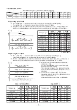
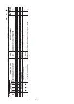
WE t
a
p
+1 t
a
p / 20 sec
Up to the m
a
ximum
revolution frequency of e
a
ch zone
Revolution frequency hold
–1 t
a
p / 20 sec
Up to the minimum
revolution frequency of e
a
ch zone
TL [˚C]
5
8
55
38
3
5
–2 t
a
ps / 20 sec. (Up to W1)
S
top timer count
+1 t
a
p / 20 sec
(Up to the m
a
ximum t
a
p of e
a
ch zone)
–2 t
a
ps / 20 sec. (Up to W1)
–1 t
a
p / 20 sec. (Up to W1)
Revolution frequency hold
TE [˚C]
24
21
1
8
15
3. Outdoor fan control
Revolution frequency allocation of fan tap
s
[rpm]
GP110 to
Up
GP160
Down
W1
W2
W3
W4
W5
W6
W7
W8
W9
WA
WB
WC
WD
WE
200
240
240
260
3
20
38
0
4
8
0
500
5
3
0
610
640
660
720
7
8
0
—
—
200
2
8
0
3
60
400
500
520
550
6
3
0
660
700
740
8
20
∗
: WB for GP110
Temp. ran
g
e
38
˚C
≤
TO
2
9
˚C
≤
TO <
38
˚C
15˚C
≤
TO < 2
9
˚C
5˚C
≤
TO < 15˚C
0˚C
≤
TO < 5˚C
–4˚C
≤
TO < 0˚C
TO < –4˚C
TO trouble
20 Hz
20Hz
45Hz
or lower
to 45Hz
or hi
g
her
Min.
Max.
Min.
Max.
Min.
Max.
W6
WC
W
8
WD
WA
WD
W5
WB
W7
WC
∗
W
9
WC
W4
W
8
W6
WA
W
8
WC
W
3
W6
W5
W
8
W7
WA
W2
W4
W4
W6
W5
W
8
W2
W
3
W
3
W5
W4
W6
W1
W2
W1
W4
W2
W6
W1
WC
W1
WD
W2
WD
Object: GP110
Object: GP140 (GP160)
Temp. ran
g
e
10˚C
≤
TO
5˚C
≤
TO < 10˚C
–
3
˚C
≤
TO < 5˚C
–10˚C
≤
TO < –
3
˚C
TO < –10˚C
TO trouble
20 Hz
20Hz
45Hz
or lower
to 45Hz
or hi
g
her
Max.
Max.
Max.
W7
W
8
W
9
W
9
WA
WB (WC)
WB (WC)
WB (WC)
WC
WC
WC
WC
WD
WD
WD
WD
WD
WD
Temp. ran
g
e
10˚C
≤
TO
5˚C
≤
TO < 10˚C
–
3
˚C
≤
TO < 5˚C
–10˚C
≤
TO < –
3
˚C
TO < –10˚C
TO trouble
20 Hz
20Hz
45Hz
or lower
to 45Hz
or hi
g
her
Max.
Max.
Max.
W7
W
8
W
9
W
9
WA
WA
WA
WA
WC
WC
WC
WC
WD
WD
WD
WD
WD
WD
3-1) Cooling fan control
c
The outdoor fan is controlled by TL sensor, TO sensor and the operation frequency.
The outdoor fan is controlled by every 1 tap of DC fan control (14 taps).
d
Only for 60 seconds after the operation has started, the maximum fan tap corresponding to the
zone in the following table is fixed and then the fan is controlled by temperature of TL sensor.
3-2) Heating fan control
c
The outdoor fan is controlled by TE sensor, TO sensor and the operation frequency.
(Control from minimum W1 to maximum (according to the following table))
d
For 3 minutes after the operation has started, the maximum fan tap corresponding to the zone in
the following table is fixed and then the fan is controlled by temperature of TE sensor.
e
When TE
≥
24°C continues for 5 minutes, the
compressor stops.
It is the same status as the normal thermostat-
OFF without trouble display.
The compressor restarts after approx. 2 minutes
30 seconds and this intermittent operation is not
abnormal.
f
In case that the status in item
e
generates
frequently, stain on filter of the suction part of the
indoor unit is considered.
Clean the filter and then restart the operation.

