– 56 –
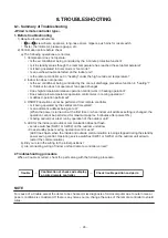
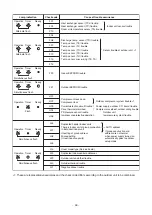
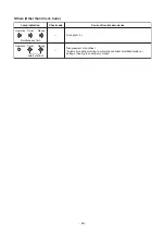
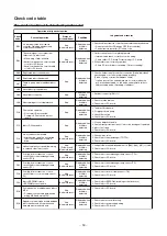
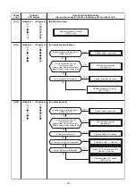
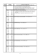
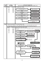
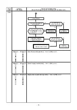
The contents of trouble detected by remote controller or central controller (TCC-LINK)
∗
1 The check code cannot be displayed by the wired remote controller.
(Usual operation of air conditioner becomes unavailable.)
For the wireless models, a trouble is notified with indication lamp.
∗
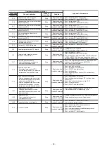
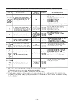
2 This trouble is related to communication of remote controller (A, B), central system (TCC-LINK U3, U4),
and [E01], [E02], [E03], [E09] or [E18] is displayed or no check display on the remote controller according
to the contents.
Operation of dia
g
no
s
tic function
S
tatu
s
of
air conditioner
Condition
Cau
s
e of operation
Check code
Jud
g
ment and mea
s
ure
s
Not displ
a
yed
a
t
a
ll
(Oper
a
tion
on remote
controller is
impossible.)
No communic
a
tion with he
a
der indoor unit
• Remote controller wiring is not correct.
• Power of indoor unit is not turned on.
• Autom
a
tic
a
ddress c
a
nnot be completed.
S
top
—
Power supply trouble of remote controller, Indoor
EEPROM trouble
1. Check remote controller inter-unit wiring.
2. Check remote controller.
3
. Check indoor power wiring.
4. Check indoor P.C. bo
a
rd.
5. Check indoor EEPROM.
(including socket insertion)
→
Autom
a
tic
a
ddress repe
a
ting phenomenon
gener
a
tes.
E01
∗
1
No communic
a
tion with he
a
der indoor unit
• Disconnection of inter-unit wire between
remote controller
a
nd he
a
der indoor unit
(Detected by remote controller side)
S
top
(Autom
a
tic reset)
∗
If centr
a
l controller
exists, oper
a
tion
continues.
Displ
a
yed
when trouble
is detected
Receiving trouble from remote controller
1. Check remote controller inter-unit wiring.
2. Check remote controller.
3
. Check indoor power wiring.
4. Check indoor P.C. bo
a
rd.
E02
S
ign
a
l send trouble to indoor unit
(Detected by remote controller side)
S
top
(Autom
a
tic reset)
∗
If centr
a
l controller
exists, oper
a
tion
continues.
Displ
a
yed
when trouble
is detected
S
ending trouble of remote controller
1. Check sending circuit inside of remote
controller.
→
Repl
a
ce remote controller.
E0
9
There
a
re multiple m
a
ster remote controllers.
(Detected by remote controller side)
S
top
(Follower unit
continues oper
a
tion.)
Displ
a
yed
when trouble
is detected
1. In 2-remote controllers (including wireless),
there
a
re multiple he
a
der units.
Check th
a
t there
a
re 1 m
a
ster remote
controller
a
nd other sub remote controllers.
L20
Centr
a
l
controller
L20
S
top
(Autom
a
tic reset)
Displ
a
yed
when trouble
is detected
1. Check setting of centr
a
l control system
network
a
ddress. (Network
a
d
a
pter
S
W01)
2. Check network
a
d
a
pter P.C. bo
a
rd.
Duplic
a
ted indoor centr
a
l
a
ddresses on
communic
a
tion of centr
a
l control system
(Detected by indoor/centr
a
l controller side)
—
∗
2
Centr
a
l
controller
(
S
end)
C05
(Receive)
C06
Continues
(By remote controller)
Displ
a
yed
when trouble
is detected
1. Check communic
a
tion wire / miss-wiring
2. Check communic
a
tion (U
3
, U4 termin
a
ls)
3
. Check network
a
d
a
pter P.C. bo
a
rd.
4. Check centr
a
l controller (such
a
s centr
a
l
control remote controller, etc.)
5. Check termin
a
l resist
a
nce. (TCC-LINK)
Communic
a
tion circuit trouble of centr
a
l
controller
(Detected by centr
a
l controller side)
—
Centr
a
l
controller
P
3
0
Continu
a
tion/
S
top
(According
to e
a
ch c
a
se)
Displ
a
yed
when trouble
is detected
Check the check code of the corresponding
unit from remote controller.
Indoor Gr sub unit trouble
(Detected by centr
a
l controller side)


