– 94 –
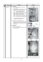
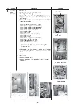
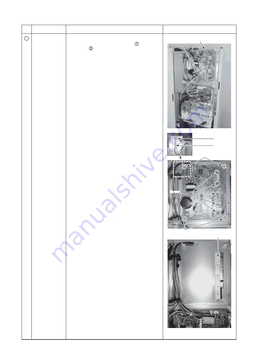
State of Fan-IPDU
b
oard when removed
Heat
s
ink
S
u
pport
(2 po
s
ition
s
)
FAN-IPDU
b
oard
Screw
Earth wire
S
u
pport
(2 po
s
ition
s
)
Screw
No.
6
Part name
Fan-IPDU
b
oard
MCC-1597
Procedure
1. Detachment
1) Carry o
u
t the operation in 1. of
, and
1. of
a
b
ove.
2) Remove lead wire
s
and connector
s
to other
component
s
from the Fan-IPDU
b
oard.
CN500 : Connection
b
etween reactor and
noi
s
e filter
b
oard (7P, Red)
CN502 : Compre
ss
or IPDU
b
oard (3P, White)
CN504 : Interface
b
oard (5P, Bl
u
e)
CN505 : Compre
ss
or IPDU
b
oard (5P, Red)
CN602 : Noi
s
e filter
b
oard (2P, Black)
CN700 : O
u
tdoor
s
lower fan motor (3P, Bl
u
e)
CN750 : O
u
tdoor
s
u
pper fan motor (3P, White)
∗
Connector
s
s
ho
u
ld
b
e removed after
u
nlocking the ho
us
ing
s
ection.
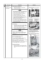
3) Remove
s
crew fixing the earth wire.
4) Remove the claw of the
su
pport (4 po
s
ition
s
)
fixing the
b
oard and the
s
crew (5 po
s
ition
s
)
fixing the heat
s
ink and then remove the Fan-
IPDU
b
oard.
2. Attachment
1) Mo
u
nt Fan-IPDU
b
oard
2) Mo
u
nt component
s
in the oppo
s
ite method to
that when removing.
Remarks

