-16-
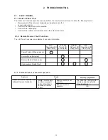
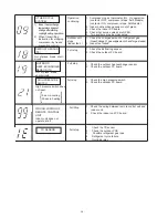
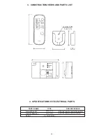
DEFROST SENSOR
(TE)
OTHER CYCLE
SYSTEM
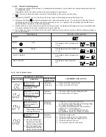
1. Compressor case thermostat, IOL, OL operation.
(contactor OFF, compressor stops: AH8 Models)
(contactor ON, compressor stops: AH Models)
2. Indoor heat-exchange sensor out of place.
3. Check the indoor PC board.
4. Check that service valves are OPEN.
5
.
Two systems may be cross wired.
1. Check the charged amount of refrigerant gas.
(Gas shortage
→
gas supplement, check for gas leaks)
2. Indoor fan locked.
1. Check the defrosting sensor.
2. Check the outdoor PC board.
Out of place, break, short-
circuit.
1) Indoor heat exchange
temperature does not
change after starting
cooling/heating operation.
2) When transmitting
instruction for stopping
compressor by freeze
preventing control.
1. Check the high pressure switch.
2. Check the outdoor PC board.
1. Check the outdoor heat-exchanger sensor.
2. Check the outdoor PC board.
Full stop
Full stop
High pressure switch does
not reset.
5 sec in cooling
30 sec in heating
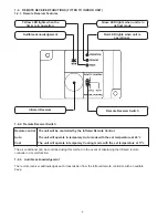
WRONG WIRING OF
REMOTE CONTROL
UNIT
Indoor unit does not
operate at all.
Out of place, break,
short-circuit.
OUTDOOR
HEAT-EXCHANGER
SENSOR (TL)
HIGH PRESSURE
SWITCH
Full Stop
1. Check the wiring between remote control unit and
indoor unit.
2. Check the indoor unit PC board.
Full stop
TD SENSOR
1. Check the TD sensor
2. Check the outdoor PCB
3. Possible refrigerant gas leak
4. Refrigerant cycle failure
5. Overload relay
Full stop
Outdoor unit
stops
(indoor fan L)
Operation
continuing


