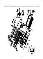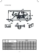
No. Part name
⑤
Fan,
Fan case,
Quantity of fan
Shaft
QTY
2
3
4
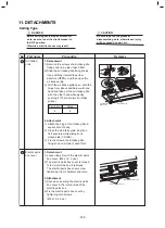
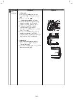
1. Detachment
NOTE
It explains the following content by
80 to 1
6
0 type.
1)
P
e
rform works of 1 of
①
and
②
.
2)
R
e
move the support plate.
(Ø4 x 10, 1 pcs.) (80-1
6
0 type only)
The
screw on a front side is removed,
and it
detaches it from the square
hole on the
back side.
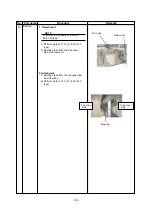
3)
R
e
move the fixing screws of
the fan case (under).
(Ø4 x 10, 1 pcs.
)
4)
T
he hanging claw on both sides of fan
case (under) is removed.
5)
F
an case (under) is pulled out from
the
partition plate, and fan case (under)
is
removed.
6)
T
he screw with the hexagonal screw
hole to of the coupling is loosened,
and
the shaft is removed with the fan.
7)
T
he screw with the hexagonal screw
hole of the fan is loosened, and the fan
is detached from the shaft.
NOTE
It explains the following content by
40 and 56 type.
1)
P
e
rform works of 1 of
①
,
②
and
③
.
2)
R
e
move connectors for fan motor
wiring
from control P.C. board.
CN210 : Fan motor (7P, White)
3)
R
e
move the fixing screws of
the fan case (under).
(Ø4 x 10, 1 pcs.)
4) T
he hanging claw on both sides of fan
case (under) is removed.
5) F
an case (under) is pulled out from
the
partition plate, and fan case (under)
is
removed.
6)
R
e
move the fixing screws of the
fixing plate (2 pcs.) at the side of the
fan
motor. (Ø5 x 10, 2 pcs.)
The earth screw is tightening together
with motor fixing screw.
7) W
hile supporting the fan motor by
hands, remove the the fan motor.
8) T
he screw with the hexagonal screw
hole of the fan is loosened, and the fan
is detached from the shaft.
Remarks
40, 56
80
90
~
1
6
0
Model
Procedure
Square hole
Support plate
Front side screw
Hanging claw
Coupling
Shaft and Fan
- 102 -


