10
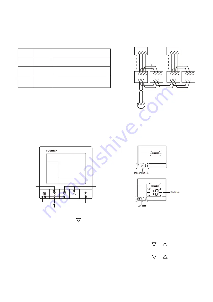
-3. Address Setup (Manual Setting from Remote Controller)
(Example of 2-lines wiring)
(Solid line: Wiring, Broken line: Refrigerant pipe)
For the above example, perform setting by
connecting singly the wired remote controller
without remote controller inter-unit wire.
Outdoor
Indoor
A B
A B
1 2 3
Indoor
A B
1 2 3
Indoor
A B
1 2 3
Indoor
A B
1 2 3
1 2 3
Outdoor
1 2 3
Remote controller
Line address
→
1
Indoor unit address
→
1
Group address
→
1
1
2
2
2
1
2
2
2
2
In case that addresses of the indoor units will be
determined prior to piping work after wiring work
• Set an indoor unit per a remote controller.
• Turn on power supply.
Indoor unit
address
Group
address
CODE No.
(DN)
Item
13
14
Description
0001: No.1 to 0128: No.128 … TU2C-Link
0001: No.1 to 0030: No.30 … TCC-Link
12
Line address
0001: No.1 to 0128: No.128 … TU2C-Link
0001: No.1 to 0030: No.30 … TCC-Link
0000: Individual
0001: Header unit
0002: Follower unit
<RBC-ASCU1
∗∗∗∗∗
>
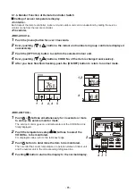
1
Push and hold the [menu +
] buttons at same time for more than 10 seconds.
2
Push the [OFF timer] button to confirm the selected indoor unit.
<Line address>
3
Push the [menu] button until the CODE No. flashes. And using the [ or
] buttons,
specify the CODE No.12.
4
Push the [menu] button until the SET DATA flashes. And using the [ or
] buttons, set
a system address.
5
Push the [OFF timer] button to confirm the SET DATA.
2
3,4
3,4
3,4
6
2,5
- 97 -


