background image

38-EN

37-EN

– 19 –

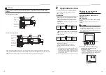
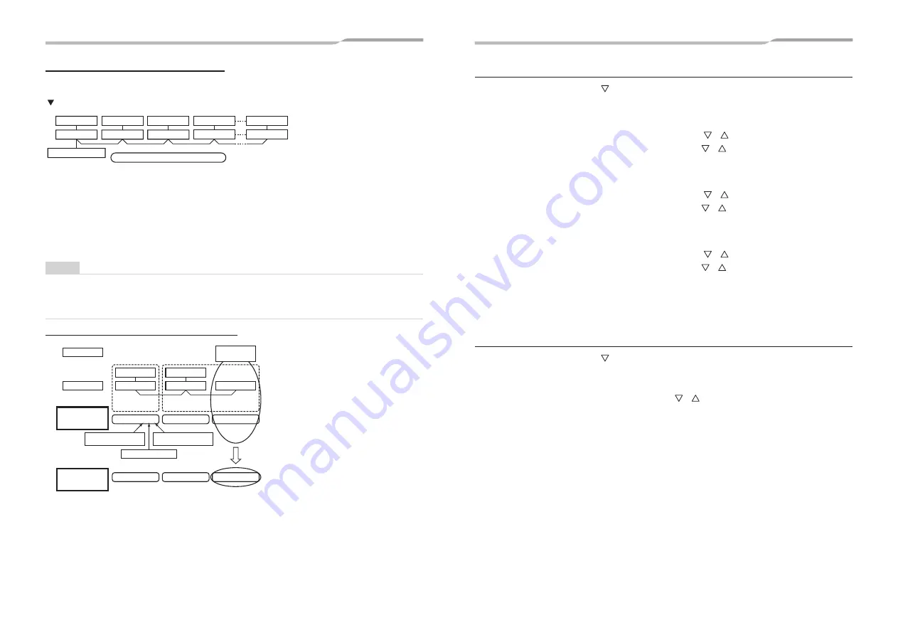
Group control for system of multiple units

One group can control up to 16 (TU2C-Link) or 8 (TCC-Link) indoor units with one remote controller. (Refer to the 
Wiring speci

fi

cations)

Indoor unit

Remote controller

Finish of address setup by power-ON

Indoor unit

Indoor unit

Indoor unit

Indoor unit

Outdoor

Outdoor

Outdoor

Outdoor

Outdoor


Group control in single system

•   

For wiring procedure and wiring method of the individual line (Identical refrigerant line) system, follow to 
“Electrical connection”.

•   

Wiring between lines is performed in the following procedure.
Connect the terminal block (A/B) of the indoor unit connected with a remote controller to the terminal blocks
(A/B) of master indoor unit of follower indoor units by wiring the inter-unit wire of the remote controller.

•   

When the power supply has been turned on, the automatic address setup starts and which indicates that address 
is being set up 

fl

ashes on the display part in about 3 minutes. During setup of automatic address, the remote 

controller operation is not accepted.

Required time up to the 

fi

nish of automatic addressing is approx. 5 minutes.

NOTE

In some cases, it is necessary to change the address manually after setup of the automatic address according to 
the system con

fi

guration of the group control.

•   

The follow mentioned system con

fi

guration is a case when complex systems in which systems of the 

simultaneous twin and simultaneous triple unit is controlled as a group by a remote controller.

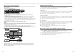
(Example) Group control for complex system

Line system

<Single system>

<Twin system>

Indoor No.

Line address

Group address

Indoor address

Address: 1-1-1

Address: 1-1-2

Outdoor unit

Indoor unit

Outdoor unit

Indoor unit

Indoor unit

Procedure

example 1

Address: 2-1-2

Address: 2-1-2

Address: 2-2-2

Address: 3-3-1

(Example of random

setup) 

(Example of address setup change)

After setup of

automatic

address

After setup

change of

manual address

The above address is set by the automatic addressing when the power is turned on. However, line 
addresses and indoor addresses are set randomly. For this reason, change the setting to match line 
addresses with indoor addresses.


„

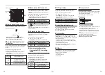
Manual address setting

1

Push and hold menu button and [

] setting button simultaneously for 10 seconds or more.

2

Push OFF timer button to con

fi

rm the selected indoor unit.

<Line address>

3

Push the menu button until the Code No. 

fl

ashes. And using the [

] [

] buttons, specify the Code No. 

[12]

.

4

Push the menu button until the Set data 

fl

ashes. And using the [

] [

] buttons, set a line address.

5

Push OFF timer button to con

fi

rm the Set data.

<Indoor unit address>

6

Push the menu button until the Code No. 

fl

ashes. And using the [

] [

] buttons, specify the Code No. 

[13]

.

7

Push the menu button until the Set data 

fl

ashes. And using the [

] [

] buttons, set an indoor unit address.

8

Push OFF timer button to con

fi

rm the Set data.

<Group address>

9

Push the menu button until the Code No. 

fl

ashes. And using the [

] [

] buttons, specify the Code No. 

[14]

.

10

Push the menu button until the Set data 

fl

ashes. And using the [

] [

] buttons, set a group address. If the

indoor unit is individual, set the address to 0000. (header unit: 0001, follower unit: 0002)

11

Push OFF timer button to con

fi

rm the Set data.

12

When all the settings have been completed, push ON/OFF button to 

fi

nish the settings.

(Return to the normal mode)


„

To 

fi

nd an indoor unit’s position from its address

1

Push and hold menu button and [

] setting button simultaneously for 10 seconds or more.

E.g.) A unit number 1-1 is indicated on the LCD of the remote controller. The indicated number shows the line 

(system) address and indoor unit address of the unit.

2

When 2 or more indoor units are connected to the remote controller (group-controlled units), a number of 
other connected units appears each time you push the [

] [

] buttons.

3

Push the ON/OFF button, return to the normal mode.

Summary of Contents for RAV-HM1101UTP-E

Page 1: ...NDITIONER SPLIT TYPE Installation Manual Indoor Unit Model name For commercial use English R32 RAV HM561UTP E RAV HM801UTP E RAV HM901UTP E RAV HM1101UTP E RAV HM1401UTP E RAV HM1601UTP E 4 way Cassette type ...

Page 2: ...rigerant HFC R32 which does not destroy the ozone layer Be sure to check the refrigerant type for outdoor unit to be combined and then install it Product information of ecodesign requirements Regulation EU 2016 2281 http ecodesign toshiba airconditioning eu en Please read this Installation Manual carefully before installing the Air Conditioner This Manual describes the installation method of the i...

Page 3: ... person who has been trained in matters relating to electrical work on the air conditioners made by Toshiba Carrier Corporation or alternatively he or she has been instructed in such matters by an individual or individuals who have been trained and is thus thoroughly acquainted with the knowledge related to this work The qualified service person who is allowed to do the refrigerant handling and pi...

Page 4: ... breaker to the OFF position Otherwise electric shocks may result Place a Work in progress sign near the circuit breaker while the installation maintenance repair or removal work is being carried out There is a danger of electric shocks if the circuit breaker is set to ON by mistake Only a qualified installer 1 or qualified service person 1 is allowed to undertake work at heights using a stand of ...

Page 5: ... unit This appliance is intended to be used by expert or trained users in shops in light industry or for commercial use by lay persons Selection of installation location When the air conditioner is installed in a small room provide appropriate measures to ensure that the concentration of refrigerant leakage occur in the room does not exceed the critical level Do not install in a location where fla...

Page 6: ...rry out the electrical work of the air conditioner Under no circumstances must this work be done by an unqualified individual since failure to carry out the work properly may result in electric shocks and or electrical leaks To connect the electrical wires repair the electrical parts or undertake other electrical jobs wear gloves to provide protection for electricians and from heat insulating shoe...

Page 7: ... to turn it off in the event that trouble has occurred in the air conditioner If the fan grille is damaged do not approach the outdoor unit but set the circuit breaker to the OFF position and contact a qualified service person 1 to have the repairs done Do not set the circuit breaker to the ON position until the repairs are completed After the installation work follow the Owner s Manual to explain...

Page 8: ...safety maintenance and check Place where drained water will not cause any problem Avoid installing in the following places Place exposed to air with high salt content seaside area or place exposed to large quantities of sulfide gas hot spring Should the unit be used in these places special protective measures are needed A restaurant kitchen where a lot of oil is used or place near machines in a fa...

Page 9: ... thick Ceiling height Model Possible installed ceiling height HM56 HM80 Type Up to 3 8 m HM90 HM110 HM140 HM160 Type Up to 4 6 m When the height of the ceiling exceeds the distance of the item Standard 4 way in Table as below the hot air is difficult to reach the floor Therefore it is necessary to change the setup value of the high ceiling switch or discharge direction The high ceiling setting is ...

Page 10: ...n After the location of the indoor unit installation has been determined open the ceiling and install hanging bolts The dimensions of the ceiling opening and hanging bolt pitches are given in the outline drawing and the attached installation pattern When a ceiling already exists lay the drain pipe refrigerant pipe indoor unit outdoor unit connection wires and remote controller wires to their conne...

Page 11: ...el according to Installation Manual attached with it after piping wiring work has completed Check that installation of indoor unit and ceiling opening part is correct and then install it REQUIREMENT Joint the connecting sections of ceiling panel ceiling surface ceiling panel and indoor unit closely Any gap between them will cause air leakage and the generate condensation or water leakage Remove th...

Page 12: ...ply a heat insulation so as not to cause a dew dropping Inappropriate piping work may result in water leakage in the room and wet of furniture Piping Heat insulating material Require the following materials for piping and heat insulating at site Piping Hard vinyl chloride pipe VP25 Outer dia Ø32 mm Heat insulator Foam polyethylene Thickness 10 mm or more Flexible hose Use the attached flexible hos...

Page 13: ...f check by pulling out the float switch connector be sure to return the connector to the original position 1 2 Power terminals CN34 RED Black Red White Black Pull out connector CN34 Red from P C board Single phase 220 240V Perform heat insulating As shown in the figure cover the flexible hose and hose band with the attached heat insulator up to the bottom of the indoor unit without gap Cover the d...

Page 14: ...e pipe with the attached heat insulator without any gap between the indoor unit The seam must be faced upward ceiling side Flare nut Indoor unit Heat insulation pipe Accessory Banding band locally procured Heat insulator of the pipe Union 7 Electrical connection WARNING Use the specified wires for wiring connect the terminals Securely fix them to prevent external forces applied to the terminals fr...

Page 15: ...for each indoor unit in the simultaneous twin simultaneous triple and simultaneous double twin systems Wiring diagram Single system Simultaneous twin system Simultaneous triple and double twin system Communication type TU2C Link can be used with these models If the indoor unit and the connected remote controller remote sensor are all TU2C Link models TU2C Link communication will be performed autom...

Page 16: ... 2 3 A B Heat insulation to wiring connecting port Adhered surface Notched section Power supply terminal block Cord clamp Remote controller terminal block Side D Space 8 5 mm Select side C or D for the power cable clamping position referring to the following table according to the cable type and diameter Cable clamp can be attached on either right or left side When twin system are connected clamp ...

Page 17: ...until the remote controller becomes available Approx 1 minutes SETTING flashes SETTING goes out Remote controller is available Power on Normal settings were made when the indoor unit was shipped from factory Change the indoor unit settings as required Use the wired remote controller to change the settings The settings cannot be changed using the wireless remote controller sub remote controller or ...

Page 18: ...re 5 1 0001 2 0002 3 0003 5 0005 4 0004 SET DATA When 4 or 5 is selected dew drop may occur during cooling mode y When the setting has been determined lights up Installing indoor unit on high ceiling When an indoor unit is installed on a ceiling higher than the standard height make the high ceiling setting for fan speed adjustment Follow to the basic operation procedure 1 2 3 4 5 6 For the CODE No...

Page 19: ...emote controller sensor 0000 Not in use Factory default 0001 In use When flashes the remote controller sensor is defective Select the set data 0000 not in use or replace the remote controller Communication type When connecting to the central control device dedicated to TCC Link it is necessary to change to TCC Link Follow to the basic opreration procedure 1 2 3 4 5 6 7 y Specify FC for the Code No...

Page 20: ...m setup Example of address setup change After setup of automatic address After setup change of manual address The above address is set by the automatic addressing when the power is turned on However line addresses and indoor addresses are set randomly For this reason change the setting to match line addresses with indoor addresses Manual address setting 1 Push and hold menu button and setting butt...

Page 21: ...es 4 5 4 5 Indicators Operation green Timer green and Ready orange in the wireless receiver section flash in approx 10 seconds and the air conditioner starts operation If any of these indicators does not flash repeat procedures 2 to 5 7 Upon completion of the test run push ON OFF button to stop operation Overview of test run operations using the wireless remote controller T Cooling test run ON OFF...

Page 22: ...nger It may differ from the actual discharge temperature 2 For outdoor unit data refer to the Installation Manual and Service Manual of the outdoor unit 10Maintenance CAUTION Before maintenance be sure to turn off the leakage breaker Cleaning of air filter Clogging of the air filter reduce cooling heating performance Cleaning of panel and air filter Preparation 1 Turn off the air conditioner by th...

Page 23: ...s the owner s expense Failure to clean the indoor and outdoor units regularly will result in poor performance freezing water leakage and even compressor failure Inspection before maintenance Following inspection must be carried out by a qualified installer or qualified service person Parts Possible installed ceiling height Heat exchanger Access from inspection opening and remove the access panel E...

Page 24: ...short circuit of the heat exchanger sensor TC was detected Auto reset F04 ALT Outdoor unit discharge temp sensor TD error Outdoor Outdoor temp sensor TD outdoor P C board Open circuit or short circuit of the discharge temp sensor was detected Entire stop F06 ALT Outdoor unit temp sensor TE TS error Outdoor Outdoor temp sensors TE TS outdoor P C board Open circuit or short circuit of the heat excha...

Page 25: ...stop due to incorrect external input into CN80 Entire stop L31 SIM Phase sequence error etc Outdoor Power supply phase sequence outdoor unit P C board Abnormal phase sequence of the 3 phase power supply Operation continued thermost at OFF P01 ALT Indoor unit fan error Indoor Indoor fan motor indoor P C board Indoor AC fan error fan motor thermal relay activated was detected Entire stop P03 ALT Out...

Page 26: ...Place Issued Masaru Takeyama GM Quality Assurance Dept 5 April 2022 Thailand NOTE This declaration becomes invalid if technical or operational modifi cations are introduced without the manufacturer s consent Declaration of Conformity Manufacturer Toshiba Carrier Thailand Co Ltd 144 9 Moo 5 Bangkadi Industrial Park Tivanon road Tambol Bangkadi Amphur Muang Pathumthani 12000 Thailand TCF holder TOSH...

Page 27: ...ity of residue shiny metal dust or other wear residue or mixture of foreign matter is observed trouble will occur 8 When temporary installation and removal of the air conditioner are repeated such as when leased etc 9 If the type of refrigerator oil of the existing air conditioner is other than the following oil Mineral oil Suniso Freol S MS Synthetic oil alkyl benzene HAB Barrel freeze ester seri...

Page 28: ...144 9 Moo 5 Bangkadi Industrial Park Tivanon Road Tambol Bangkadi Amphur Muang Pathumthani 12000 Thailand 1115350191 ...

Reviews: