background image

Installation Manual

 13 

13-EN

„

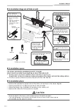
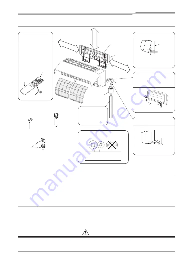
Installation diagram of Indoor unit

50 mm or more

300 mm or more

170 mm or more

Shield 
pipe

Hook

Installation 
plate

Air 

fi

 lter

(Attach to the front 

panel.)

Hook

*1

*2

The auxiliary piping can be 
connected to the left, rear left, 
rear right, right, bottom right or 
bottom left.

Right

Rear right

Bottom
right

Rear
left

Bottom left

Left

Insulate the refrigerant pipes separately 
with insulation, not together.

6 mm thick heat resisting
polyethylene foam

Insert the cushion between the 
indoor unit and wall, and tilt the 
indoor unit for better operation.

For the rear left and left piping

Wall

Make sure to run the drain hose 
sloped downward.

Do not allow the drain hose to 
get slack.

Cut the piping 
hole sloped 
slightly.

Batteries

Wireless 
remote controller

Remote control holder

Flat head 
wood screw

Refrigerant piping 
must be protected 
from physical damage.
Install a plastic cover 
or equivalent.

Before installing the 
wireless remote controller

1. Remove the battery 

cover.

2. Insert 2 new batteries 

(R03 [AAA] type) 
following the (+) and (

positions.

Wireless 
remote controller

Cover

Batteries

Heat insulator

„

Installation space

The indoor unit shall be installed at least 2.5 m height.
Also it must be avoided to put anything on top of the indoor unit.

*1  Reserve space required to install the indoor unit and for service work.


Keep 50 mm or more for clearance between top plate of the indoor unit and the ceiling surface.

*2  Provide a space as shown for service clearance for the cross 

fl

ow fan.

„

Installation place

•  A place which provides the spaces around the indoor unit as shown in the above diagram.
•  A place where there is no obstacle near the air inlet and outlet.
•  A place that allows easy installation of the piping to the outdoor unit.
•  A place which allows the front panel to be opened.

 CAUTION

•  Direct sunlight to the indoor unit’s wireless receiver should be avoided.
•  The microprocessor in the indoor unit should not be too close to RF noise sources.
  (For details, see the owner’s manual.)

Summary of Contents for RAV-HM561KRTP-E

Page 1: ...Installation Manual Indoor Unit High Wall Type Model name RAV HM561KRTP E RAV HM801KRTP E RAV HM901KRTP E Installation Manual 1 English For commercial use R32 ...

Page 2: ...ich does not destroy the ozone layer Be sure to check the refrigerant type for outdoor unit to be combined and then install it Product information of ecodesign requirements Regulation EU 2016 2281 http ecodesign toshiba airconditioning eu en Contents 1 PRECAUTIONS FOR SAFETY 5 2 ACCESSORY PARTS 11 3 SELECTION OF INSTALLATION PLACE 12 4 INSTALLATION OF INDOOR UNIT 14 5 CUTTING A HOLE AND MOUNTING I...

Page 3: ... or alternatively he or she has been instructed in such matters by an individual or individuals who have been trained and is thus thoroughly acquainted with the knowledge related to this work The qualified installer who is allowed to work at heights has been trained in matters relating to working at heights with the air conditioners made by Toshiba Carrier Corporation or alternatively he or she ha...

Page 4: ...on Meaning of Indication WARNING Text set off in this manner indicates that failure to adhere to the directions in the warning could result in serious bodily harm 1 or loss of life if the product is handled improperly CAUTION Text set off in this manner indicates that failure to adhere to the directions in the caution could result in slight injury 2 or damage 3 to property if the product is handle...

Page 5: ...ving parts Do not operate unit with grille removed Stop the unit before the servicing CAUTION High temperature parts You might get burned when removing this panel CAUTION High temperature parts You might get burned when removing this panel CAUTION Do not touch the aluminum fins of the unit Doing so may result in injury CAUTION Do not touch the aluminium fins of the unit Doing so may result in inju...

Page 6: ...allowed to do installation work Inappropriate installation may result in water leakage electric shock or fire Do not use any refrigerant different from the one specifled for complement or replacement Otherwise abnormally high pressure may be generated in the refrigeration cycle which may result in a failure or explosion of the product or an injury to your body Before opening the front panel of the...

Page 7: ...r or other parts of the outdoor unit set the circuit breaker to OFF without fail and place a Work in progress sign near the circuit breaker before proceeding with the work Before working at heights put a sign in place so that no one will approach the work location before proceeding with the work Parts and other objects may fall from above possibly injuring a person below While carrying out the wor...

Page 8: ...and cause a fire Install the indoor unit at least 2 5 m above the floor level since otherwise the users may injure themselves or receive electric shocks if they poke their fingers or other objects into the indoor unit while the air conditioner is running Installation Install the air conditioner securely in a location where the base can sustain the weight adequately If the strength is not enough th...

Page 9: ...ied service person 1 is allowed to carry out the electrical work of the air conditioner Under no circumstances must this work be done by an unqualified individual since failure to carry out the work properly may result in electric shocks and or electrical leaks To connect the electrical wires repair the electrical parts or undertake other electrical jobs wear gloves to provide protection for elect...

Page 10: ...for instance until qualified service person 1 arrives Continuing to use the air conditioner in the trouble status may cause mechanical problems to escalate or result in electric shocks or other trouble After the work has finished use an insulation tester set 500V Megger to check the resistance is 1 MΩ or more between the charge section and the non charge metal section earth section If the resistan...

Page 11: ...m oil etc due to the high pressure be careful not to allow the moisture dirt existing refrigerant refrigerating machine oil etc to get mixed up in the refrigeration cycle during the installation work A special tool for the R32 refrigerant is required for installation Use a new and clean piping materials for the connecting pipe so that moisture and dirt are not mixed together during the installatio...

Page 12: ...ual please refer to the enclosed CD R Owner s Manual 1 Hand over to customers For other languages that do not appear in this Owner s Manual please refer to the enclosed CD R CD ROM 1 Owner s Manual and Installation Manual Installation plate 1 Wireless remote controller 1 Battery 2 Remote controller holder 1 Mounting screw Ø4 25R 6 Flat head wood screw Ø3 1 16R 2 Screw Ø4 10R 2 Heat insulator 1 ...

Page 13: ...here vapors from food oils are formed such as kitchens where food oils are used Blocked filters may cause the air conditioner s performance to deteriorate condensation to form the plastic parts to be damaged and other such problems to result Locations near obstructions such as ventilation openings or lighting fixtures where the flow of the blown air will be disrupted a disruption of the air flow m...

Page 14: ...ver or equivalent Before installing the wireless remote controller 1 Remove the battery cover 2 Insert 2 new batteries R03 AAA type following the and positions Wireless remote controller Cover Batteries Heat insulator Installation space The indoor unit shall be installed at least 2 5 m height Also it must be avoided to put anything on top of the indoor unit 1 Reserve space required to install the ...

Page 15: ... specified installation work to guard against strong wind or earthquake An incomplete installation can cause accidents by the units falling and dropping REQUIREMENT Strictly comply with the following rules to prevent damage of the indoor units and human injury Do not put a heavy article on the indoor unit Even units are packaged Carry in the indoor unit as it is packaged if possible If carrying in...

Page 16: ...ock brick concrete or similar type walls make 5 mm dia holes in the wall Insert clip anchors for appropriate mounting screws NOTE Secure four corners and lower parts of the installation plate with 6 mounting screws to install it Cutting a hole In case of installing the refrigerant pipes from the rear 1 Decide the hole position for piping at 180 mm from the arrow mark Ö on the installation plate an...

Page 17: ...e slit on the bottom left or right side of the front panel for the bottom left or right connection with a pair of nippers 2 Changing drain hose For leftward connection bottom leftward connection and rear leftward connection s piping it is necessary to change the drain hose and drain cap How to remove the drain hose The drain hose can be removed by removing the screw securing the drain hose and the...

Page 18: ...Application causes deterioration and drain leakage from the plug CAUTION Firmly insert the drain hose and drain cap otherwise water may leak How to remove the drain hose 1 Remove the front panel 2 Remove the screws of drain hose 3 Pull out the drain hose How to fix the drain hose 1 Put the drain hose 2 Screw the drain hose to the indoor unit 3 Install the front panel T In case of right or left pip...

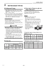
Page 19: ...he wall When bending the connecting pipe make sure to use a spring bender so as not to crush the pipe Bend the connecting pipe within a radius of 30 mm To connect the pipe after installation of the unit figure 570 mm 420 mm 43 mm Liquid side Gas side To the forefront of flare Outward form of indoor unit R 30 mm Use polisin polyethylene core or the like for bending pipe Use the handle of screwdrive...

Page 20: ...es make sure the slit aperture toward the ceiling surface CAUTION Bind the auxiliary pipes two and power supply wiring and control wiring with facing tape tightly In case of leftward piping and rear leftward piping bind the auxiliary pipes two only with facing tape Indoor unit Power supply wiring Control wiring Auxiliary pipes Installation plate Carefully arrange pipes so that any pipe does not st...

Page 21: ...t and the installation plate Especially when the pipes are pulled out from the left side the unit must be screwed to the installation plate Screw Screw 1 Run the drain hose sloped downwards NOTE Hole should be made at a slight downward slant on the outdoor side 2 Put water in the drain pan and make sure that the water is drained out of doors 3 When connecting extension drain hose insulate the conn...

Page 22: ... unit 3 Evacuate the air in the connecting pipes by using VACUUM PUMP 4 Check the gas leakage Connected points Pipe size dia mm RAV PIPE SIZE mm Gas side Liquid side HM56 12 7 6 4 HM80 90 15 9 9 5 Permissible Piping Length and Height Difference They vary according to the outdoor unit For details refer to the Installation Manual attached to the outdoor unit Flaring ෬ Cut the pipe with a pipe cutter...

Page 23: ...ghten the flare nut as far as possible with your fingers Then tighten the nut with a spanner and torque wrench as shown in the figure Work using double spanner REQUIREMENT Tightening with an excessive torque may crack the nut depending on installation conditions Tighten the nut within the specified tightening torque Piping with outdoor unit Shape of valve differs according to the outdoor unit For ...

Page 24: ...rollers for the respective air conditioners when the 2 air conditioners are closely installed Wireless remote controller B setup 1 Push TEMPORARY button on the indoor unit to turn the air conditioner ON 2 Point the wireless remote controller at the indoor unit 3 Push and hold button on the wireless remote controller by the tip of the pencil 00 will be shown on the display 4 Push during pushing B w...

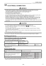
Page 25: ...ll fail Do not damage or scratch the conductive core and inner insulator of power and Indoor Outdoor connecting wires while peeling them Perform the electric wiring so that it does not come to contact with the high temperature part of the pipe The coating may melt resulting in an accident Do not turn on the power of the indoor unit until vacuuming of the refrigerant pipes completes Wiring specific...

Page 26: ...remote controller RBC A U This letter indicates U series model Other than U series Wireless remote controller kit receiver unit RBC AXU This letter indicates U series model Other than U series Remote sensor TCB TC U This letter indicates U series model Other than U series CAUTION When connecting to the central control device dedicated to TCC Link it is necessary to change to TCC Link using a wired...

Page 27: ...r side Indoor Outdoor connecting wires Power supply Indoor power inter unit wiring Indoor side T Simultaneous triple and double twin system A B 1 2 3 A B 1 2 3 A B 1 2 3 A B 1 2 3 1 2 3 Indoor side Outdoor side Remote controller Remote controller wiring Indoor Outdoor connecting wires Power supply Indoor side Indoor side Indoor side Indoor power inter unit wiring Indoor power inter unit wiring Ind...

Page 28: ...ller wire has non polarity there is no problem if connections to indoor unit terminal blocks A and B are reversed T Wiring diagram A B A B Terminal block for remote controller wiring of indoor unit Wired remote controller wire Procured locally Terminal block Wired remote controller unit ...

Page 29: ...grille upward and pull it toward you 2 Remove the terminal cover and the clamp base 3 Insert the power supply wire and control wire according to the local rule into the pipe hole on the wall 4 Take the power supply wire out of the cable slot on the rear panel so that it protrudes about 150 mm from the front 5 Insert the control wire fully into the control wired remote controller terminal block U3 ...

Page 30: ...ocal rule into the pipe hole on the wall 4 Take the Indoor Outdoor connecting wires and wired remote controller wire out of the cable slot on the rear panel so that it protrudes about 150 mm from the front 5 Insert the wired remote controller wire fully into the wired remote controller central control terminal block A B and secure it tightly with screws Strip off approx 9 mm the wire to be connect...

Page 31: ...actory Change the indoor unit settings as required Use the wired remote controller to change the settings The settings cannot be changed using the wireless remote controller sub remote controller or remote controller less system for central remote controller only Therefore install the wired remote controller to change the settings Applicable controls setup settings at the site Remote controller mo...

Page 32: ...her indoor unit repeat from Procedure 1 Change of lighting time of filter sign According to the installation condition the lighting time of the filter sign Notification of filter cleaning can be changed Follow to the basic operation procedure 1 2 3 4 5 6 For the CODE No in Procedure 4 specify 01 For the SET DATA in Procedure 5 select the SET DATA of filter sign lighting time from the following tab...

Page 33: ...y 9A for the Code No in Procedure 4 Select the following data for the set data in Procedure 5 Set data Fan speed when thermostat OFF in cooling mode 0000 Remote controller setting 0001 Extremely low speed UL Factory default 8 C operation Pre heating operation can be set for cold regions where room temperature drops to below zero Follow to the basic opreration procedure 1 2 3 4 5 6 7 Specify d1 for...

Page 34: ...ic address setup starts and which indicates that address is being set up flashes on the display part During setup of automatic address the remote controller operation is not accepted Required time up to the finish of automatic addressing is approx 5 minutes Adjustment of air direction 1 Using the remote controller switch change the up down air direction by moving the horizontal louver 2 Adjust the...

Page 35: ...bout 3 minutes During setup of automatic address the remote controller operation is not accepted Required time up to the finish of automatic addressing is approx 5 minutes NOTE In some cases it is necessary to change the address manually after setup of the automatic address according to the system configuration of the group control The follow mentioned system configuration is a case when complex s...

Page 36: ...button until the Code No flashes And using the buttons specify the Code No 14 10 Push the menu button until the Set data flashes And using the buttons set a group address If the indoor unit is individual set the address to 0000 header unit 0001 follower unit 0002 11 Push OFF timer button to confirm the Set data 12 When all the settings have been completed push ON OFF button to finish the settings ...

Page 37: ...ng for central control The terminal block for central control wiring U3 and U4 is the same as that for optional wired remote controller Connect the central control wire to the terminals U3 and U4 on the terminal block in the same way as the optional wired remote controller For details refer to the installation manual of the applicable central control system Wired remote controller wire Terminal bl...

Page 38: ...ystem 4 Central control device Central control device Central control device Up to 10 units Outdoor unit Indoor Outdoor connecting wires AC 220 240V serial Central control wires Connect 1 and 2 only Follower indoor unit Follower indoor unit Indoor unit Follower indoor unit Header indoor unit Header indoor unit TCC LINK adapter option Required for indoor units other than high wall type Remote contr...

Page 39: ... detach the electrical control box 4 Remove the electrical control box cover and set bit1 of SW01 on the board to ON Do not touch SW02 as it is used for other setting SW01 OFF SW02 OFF SW01 ON SW02 OFF ON 1 2 ON 1 2 Factory default After setting 5 Assemble the removed parts by reversing steps 1 to 3 Insert the sensors and motor lead louver motor fan motor into the original positions CAUTION Connec...

Page 40: ... central control addresses End Line address manual setting change Are indoor units under group control Are all indoor units under central control set to header units group address 1 Set indoor units under central control to header units again and set those that are out of central control to follower units again Refer to Manual address setup procedure No Refer to the manual of the central control s...

Page 41: ... executed in the following procedure even if the operation stops by thermostat OFF In order to prevent a serial operation the forced test run is released after 60 minutes have passed and returns to the usual operation CAUTION Do not use the forced test run for cases other than the test run because it applies an excessive load to the devices Wired remote controller Be sure to stop the air condition...

Page 42: ...mp setup buttons 5 Cooling test run Heating test run After confirming a signal receiving sound beep immediately set the temperature to 17 C with the temp setup buttons After confirming a signal receiving sound beep immediately set the temperature to 30 C with the temp setup buttons 6 Repeat procedures 4 5 4 5 Indicators Operation green Timer green and Ready orange in the wireless receiver section ...

Page 43: ...placing the High effciency filter or opening the service panel After the test run reset the circuit breaker of the indoor unit Monitoring function This function can be used to call the service monitor mode from the remote controller during a test run to obtain the temperature of the sensors of the remote controller indoor unit and outdoor unit 2 4 3 5 1 1 2 4 Indoor unit number Data Monitoring fun...

Page 44: ...P button of the remote controller to check an operation can also start by the remote controller Cooling operation by the remote controller may be unavailable according to the temperature conditions Check wiring piping of the indoor and outdoor units in forced cooling operation Indoor unit data Code No Data name 01 Room temperature remote controller 02 Indoor unit intake air temperature TA 03 Indoo...

Page 45: ...aise the hook on the lower centre of the air filter The air intake grille should not be opened further otherwise the arms may come off and the air intake grille may fall down Air filter Cleaning with water or vacuum cleaner If dirt is heavy clean the air filter by tepid water with neutral detergent or water After cleaning with water dry the air filter sufficiently in a shade place Mount the air fi...

Page 46: ... motor Access from inspection opening and check if any abnormal noise can be heard Fan Access from inspection opening and remove the access panel Examine the fan if there are any waggles damages or adhesive dust Filter Go to installed location and check if there are any stains or breaks on the filter Drain pan Access from inspection opening and remove the access panel Check if there is any cloggin...

Page 47: ... and the indicators appear as an image indicating the troubleshooting history mode has been entered If Service check is displayed the mode enters in the troubleshooting history mode 01 Order of troubleshooting history appears in the temperature indicator The OFF timer indicator alternately shows the check code and the indoor Unit No in which the problem occurred 2 Each time the setting button is p...

Page 48: ...g alarm and follower indoor units continue to operate Е10 CPU CPU communication error Indoor Indoor P C board Communication error between main MCU and motor microcomputer MCU Auto reset E11 Communication trouble between Application control kit and Indoor unit Indoor Communication trouble between Application control kit and Indoor unit Entire stop E18 Header unit follower unit regular communication...

Page 49: ...r a phase loss was detected Entire stop H04 Case thermostat operation Outdoor Malfunction of the case thermostat Entire stop H06 Outdoor unit low pressure system error Outdoor Current high pressure switch circuit outdoor P C board Pressure sensor error was detected or low pressure protective operation was activated Entire stop L03 SIM Duplicated header indoor units Indoor Indoor address setting er...

Page 50: ...on of the indoor fan motor indoor P C board or indoor DC fan over current or lock etc is detected Entire stop P15 ALT Gas leakage detected Outdoor There may be gas leakage from the pipe or connecting part Check for gas leakage Entire stop P19 ALT 4 way valve error Outdoor Indoor 4 way valve indoor temp sensors TC TCJ An error was detected due to temperature drop of the indoor unit heat exchanger s...

Page 51: ...Installation Manual 50 50 EN Model Sound pressure level dBA Weight kg Cooling Heating RAV HM561KRTP E 14 RAV HM801KRTP E 14 RAV HM901KRTP E 14 Under 70 dBA 15 SPECIFICATIONS ...

Page 52: ...Generic Denomination Air Conditioner Model type RAV HM561KRTP E RAV HM801KRTP E RAV HM901KRTP E Commercial name Digital Inverter Series Super Digital Inverter Series Air Conditioner Complies with the provisions of the Machinery Directive Directive 2006 42 EC and the regulations transposing into national law Name Position Date Place Issued Masaru Takeyama GM Quality Assurance Dept 5 April 2022 Thai...

Page 53: ...by declares that the machinery described below Generic Denomination Air Conditioner Model type RAV HM561KRTP E RAV HM801KRTP E RAV HM901KRTP E Commercial name Digital Inverter Series Super Digital Inverter Series Air Conditioner Complies with the provisions of the Supply of Machinery Safety Regulations 2008 Name Position Date Place Issued Masaru Takeyama GM Quality Assurance Dept 5 April 2022 Thai...

Page 54: ...lity that a large quantity of dirty oil or moisture remains inside the pipes 5 When a commercially available dryer is attached to the existing pipes There is the possibility that copper green rust has been generated 6 When the existing air conditioner is removed after refrigerant has been recovered Check if the oil is judged to be clearly different from normal oil The refrigerator oil is copper ru...

Page 55: ... y Re machine the flare machining size to size for R32 y Airtight test Vacuum dry Refrigerant charge Gas leak check Test run Was largely discolored oil or a large quantity of remains discharged When the oil deteriorates the color of the oil changes to a muddy or black color Existing pipes Cannot be used y Use new pipes Clean the pipes or use new pipes Piping necessary to change the flare nut machi...

Page 56: ...144 9 Moo 5 Bangkadi Industrial Park Tivanon Road Tambol Bangkadi Amphur Muang Pathumthani 12000 Thailand 1122750197 ...

Reviews: