Installation Manual
‒
26
‒
26-EN
Wiring between indoor unit and outdoor unit
1
Figure below shows the wiring connections between the indoor and outdoor units and
between the indoor units and remote controller. The wires indicated by the broken lines or
dot-and-dash lines are provided at the locally.
2
Refer to the both indoor and outdoor unit wiring diagrams.
3
The power of the indoor unit is supplied from the outdoor unit.
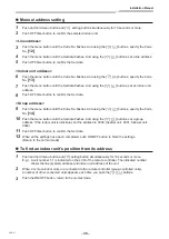
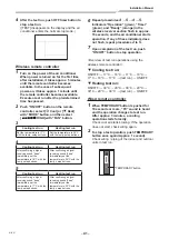
Wiring diagram
T
Single system
T
Simultaneous twin system
A B
1
1
2
2
3
3
Remote controller
Remote controller wiring
Indoor side
Outdoor side
Indoor / Outdoor
connecting wires
Power supply
A B
1
2
3
A B
1
1
2
2
3
3
Remote controller
Remote controller
inter-unit wiring
Remote controller wiring
Indoor side
Outdoor side
Indoor / Outdoor connecting
wires
Power supply
Indoor power
inter-unit wiring
Indoor
side
T
Simultaneous triple and double twin system
A B
1
2
3
A B
1
2
3
A B
1
2
3
A B
1
2
3
1
2
3
Indoor side
Outdoor side
Remote controller
Remote controller
wiring
Indoor / Outdoor
connecting wires
Power supply
Indoor
side
Indoor
side
Indoor
side
Indoor power
inter-unit wiring
Indoor power
inter-unit wiring
Indoor power
inter-unit
wiring
Remote
controller
inter-unit
wiring
Remote
controller
inter-unit
wiring
Remote
controller
inter-unit
wiring
Triple
Double twin
* Use 2-core shield wire (MVVS 0.5 to 2.0 mm² or more) for the remote controller wiring in the
simultaneous twin, simultaneous triple and simultaneous double twin systems to prevent noise
problems. Be sure to connect both ends of the shield wire to earth leads.
* Connect earth wires for each indoor unit in the simultaneous twin, simultaneous triple and simultaneous
double twin systems.


