– 21 –
8-3-4. Compressor does not Operate.
< Preliminary checks >
(1) Is the temperature set on the remote control higher than the room temperature in cool operation?
(2) Is contact of the crossing wiring O.K.?
< Check procedure >
Does power relay RY07 switch due
to temperature adjustment?
Replace thermo
sensor or heat
exchanger sensor.
Does the OPERATION lamp flash?
Is the resistance value of the thermo
sensor (TA) and heat exchanger sensor
(TC) normal?
Is 220/ 230/ 240V AC
supplied between terminal blocks and ?
Thermo sensor or heat exchanger
sensor is failure.
Replace
PC board.
Replace
power relay.
Microcomputer
is failure.
Power relay RY07
is failure.
Normal voltage value under
power relay ON condition.
Point for placing the tester bar
Polarity : +
Condition
Polarity : -
Pin 6 of
RY07
2
1
DC 12V
Normal voltage
value
YES
YES
Outdoor unit is
failure.
NO
NO
YES
NO
YES
Approximate resistance value of the sensor
10 C
20 C
30 C
20.7k
Ω
12.6k
Ω
7.97k
Ω
Refer to "Power cannot be turned on".
NO
Turn the power ON.
RY07 ON
Pin 5 of
RY07
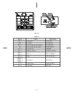
8-4. Test Points on the PC Board and List of Voltage Values
The test points (TP) are indicated on the rear of the PC board.
The voltage values on the test points for defect diagnosis items are listed below.
Table 8-6
Either end of PTH
Defect diagnosis item
Does the power relay (RY07) switch?
Is the voltage of the secondary side of
the transformer O.K.?
Is the voltage of the primary side of
the transformer O.K.?
Are both PTH terminals 5V AC or less?
Polarity (–)
Pin 5 of RY07
TP5
TP2
Point for placing the tester bar
Condition
When relay
RY07 is ON.
–
–
–
Normal voltage value
12V DC
(When relay is ON.)
No load:
14 ± 2V
With load:
12 ± 2V
(Primary voltage is
about 230V)
220-240V AC
5V AC or less: normal
5V AC or more: abnormal
Polarity (+)
Pin 6 of RY07
TP3
TP1

