– 5 –
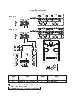
3. WIRING DIAGRAM
Shows terminal block and figures show terminal numbers.
Broken lines show wiring at site.
Don't operate the units with the magnetic contactor pushed.
Symbol
Name
CM1, 2
Compressor
FMo
Fan moter
RCc1, 2
Running capacitor (Compressor)
Symbol
Name
RCo
Running capacitor (Fan motor)
51C1, 2
Overload relay
52C1, 2
Magnetic contacto
11
L
N
12
CM1
RCo1
RCo
WHI
BLK
BLK
RED
RED
51C1
52C1
52C2
220-240V 1Ph 50Hz
power supply
Outdoor Unit
Earth screw
Indoor Unit
13
14
15
16
6
11
12
CM2
RCo2
WHI
BLK
BLK
RED
RED
51C2
13
14
A
B
5
4
3
2
1
6
5
4
3
2
1
FMo
1
2
1
52C1
A
B
52C2
Unit A
Unit B
2
1
2
1
2
A
B
1
2
1
52C1
A
B
52C2
Unit A
Unit B
2
1
2
1
2
(Electrical Parts Box)
Parts Position
(Fan Motor, Compressor,Coil)
RCo
52C2
RCc2
RCc1
52C1
N
L
2
1
2
1
CM1
FMo
CM2
Outdoor Unit
Indoor Unit
A
N
220-240V 1Ph 50Hz
power supply
Earth screw
RAV-M242A
RAV-M242A-E
Summary of Contents for RAV-M242A
Page 23: ... 23 7 5 P C Board Layout Top View Bottom View ...
Page 28: ......


